Every hole in the bay floor
Every hole that goes through the water bay floor, in one place: the layout to mark against, what each one is, how a hole gets made in a 2 1/4 in sandwich floor, and then hole by hole in order. The arguments behind the decisions are folded away at the end of each section.
1The patch
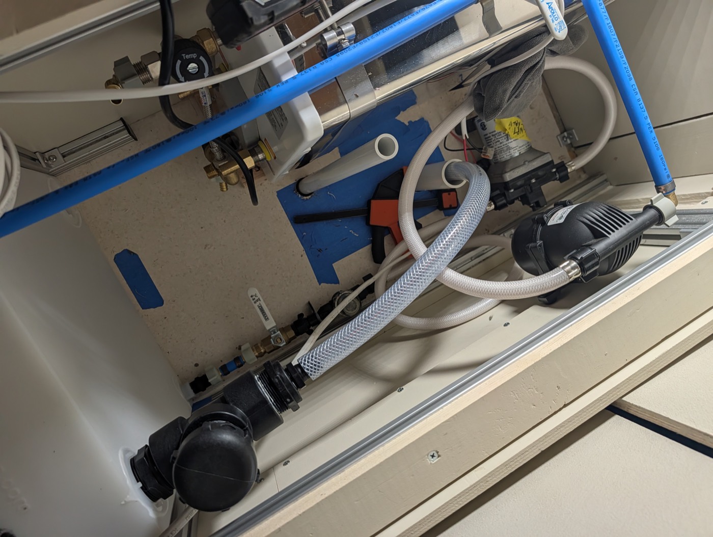
Jeff, looking at that: "It is starting to look a little wild in here." Which is the real constraint on the rear row. Every line coming up through these holes has to arrive somewhere a hand still fits, and the bay is filling from the top down while the holes are being cut from the bottom up. Cut them in the order below, and dry fit what sits above each one before committing the saw.
- 6 by 12 in of floor with nothing underneath in the way. Eight holes and their clearances live in half a square foot.
- 0.75 in clear between hole edges, 0.5 in from the patch edge. That buys saw clearance, a bead of sealant round each sleeve and room for a clamp below.
- Positions are proposed. Two things move them: what the pilot hole finds underneath, and where the strut runs. Mark them all, stand back, then drill.
2The eight holes
| # | id | what | saw | sleeve | line through it | row | done |
|---|---|---|---|---|---|---|---|
| 1 | H-1 | Isotemp safety valve drain | 1 1/8 | 3/4 in PVC Sch 40 | 1/2 in PEX | front | CUT |
| 2 | H-2 | Coolant SUPPLY to the engine | 1 3/8 | 1 in galvanised steel pipe nipple | 5/8 in ID | front | |
| 3 | H-3 | Coolant RETURN from the engine | 1 3/8 | 1 in galvanised steel pipe nipple | 5/8 in ID | front | |
| 4 | H-4 | Tank vent, and it is the overflow too | 2 | 1-1/4 in PVC Sch 40 | 3/4 in ID | front | |
| 5 | H-5 | Fill hose, inside a rigid sleeve | 2 | 1-1/4 in PVC Sch 40 | 3/4 in ID | rear | CUT |
| 6 | H-6 | Outdoor shower HOT | 1 1/4 | 3/4 in PVC Sch 40 | 1/2 in | rear | |
| 7 | H-7 | Outdoor shower COLD | 1 1/4 | 3/4 in PVC Sch 40 | 1/2 in | rear | |
| 8 | H-8 | BAY EMERGENCY DRAIN, nothing runs through it | 2 | 1-1/4 in PVC Sch 40 | 1-1/4 in bore | rear |
Three saws cover all eight: 2 in, 1 3/8 in, 1 1/4 in, 1 1/8 in. Two lengths of PVC and a bit of conduit cover every sleeve.
3How a hole is made
Same nine steps every time. Only the saw and the sleeve change.
- 1. Pilot it. 1/8 in bit, from inside, all the way through.
- 2. Go underneath and look. Every time, even the last one. Crossmembers, the box, the strut, wiring, fuel and brake lines, exhaust.
- 3. Cut from inside until the saw bottoms out.
- 4. Finish from underneath, pilot running in the hole you just made. The two cuts meet. 2 1/4 in of floor is deeper than a saw cuts.
- 5. Clean it. Vacuum the foam dust, break both edges.
- 6. Bed the sleeve. Cut it 3 in long, scuff the outside with 80 grit, wipe with alcohol, bead of sealant near the top, push it through with a twist, fillet both faces. Cure before water. On H-4, H-5, H-8 the annulus is 0.17 in on a side, so the sleeve will NOT hold itself centred: three shims at 120 degrees, check it plumb from two directions, pull them once it has cured.
- 7. Pass the line. One continuous length. No joint inside the floor, ever.
- 8. Seal the annulus at the TOP only. Foam backer pushed down first, sealant on top of it, tooled concave. Bottom stays open so a weep drains and shows. Both annuli get this: sleeve to floor, and line to sleeve bore. One rule for the whole penetration, sealed on top, open below.
- 9. Clamp the line within a foot below, its own cushioned P-clamp, onto the aluminium angle rather than the strut.
- 10. Through the box wall, for the three lines that end inside it. This is thin ALUMINIUM sheet, not the floor, so it is a different job: see below.
Why the vent gets a screen and the drain gets nothing
H-4 and H-1 are two open outlets a few feet apart and they get opposite treatment, which looks like an inconsistency and is not. What differs is what would actually block each one.
H-4, the vent, is a dry air passage that sits still for weeks at a time. Its realistic blocker is an insect walking in, and a blocked vent is the path to a split tank. So it gets a screen.
H-1, the safety valve drain, wets itself every heat cycle, points straight down and lives in the road-spray zone, which is not what an insect is looking for. Here the screen would be the blocker: the weep carries dissolved minerals and a screen is exactly where scale builds, and it faces up at road mud. So it gets nothing at all, which is also the general rule for a relief outlet.
Same question, opposite answers, because the failure mode is not the same one.
Cutting the three holes in the back of the box
The box is aluminium. Jeff put a magnet on it 2026-09-20 and it did not stick, which settles a question the page had been quietly assuming the wrong way round. It changes the lubricant, it removes the rust problem, and it introduces a galvanic one.
Size the hole to the GROMMET, not to the line. The kit grommets have a panel-hole diameter of their own. Cut to the hose OD and the grommet will not seat, and an oversized hole in a wall is not something you can take back.
A step bit, not a hole saw. In sheet this thin a hole saw catches its teeth and kicks; a step bit cannot. It also leaves a round hole rather than a slightly out-of-round one, which is what a grommet needs to seal against, and it deburrs as it steps. One bit reaching 1-3/8 does all three holes here.
It will snatch. Aluminium self-feeds: the flutes bite and pull the cutter through rather than waiting to be pushed. Hold the drill properly and ease off as you break through. This is the one that hurts people.
WD-40 or kerosene, not cutting oil. Aluminium gums and welds its chips to the cutter, and thin oil is what stops that. Heavy sulfurised cutting oil is for steel and makes this worse.
Deburr both faces. Aluminium throws a bigger, softer burr than steel does, and a burr in a hole a hose passes through is a hose that gets sawn in half over a few thousand miles of washboard. No edge paint though: it cannot rust.
Vacuum every chip out of the box, and mean it. Steel swarf left sitting on a damp aluminium floor pits it. Same reason any steel or stainless hardware you mount inside wants a plastic or EPDM washer between it and the wall.
Method otherwise: check what is behind the spot, centre punch, clamp a block of scrap tight behind the sheet, pilot at 1/8, then the step bit. Put the holes as HIGH in the back wall as the routing allows, because the grommet seals the hole but nothing keeps spray and standing water away from a hole cut low.
Why a sleeve and not epoxy, and the grommet question
Potting exists to stop a foam core crushing under something bolted through it. Nothing here bolts to the floor: every line passes through and is held by a clamp below. The sleeve covers the cut foam, the line never touches the core, and it is better than epoxy at the thing that actually happens, which is a hose sawing on a bore for ten thousand miles. It is also about fifteen dollars against sixty: potting all eight would take 25.7 cubic inches of epoxy, about 422 ml, and a cartridge holds 190.
Sealant does not stick to PEX, and nothing you buy will change that. PEX is cross-linked polyethylene, a polyolefin, and polyurethane sealant does not bond to polyolefins. Sika's own adhesion tables leave PE and PP off the list. Around the PVC bore the Sikaflex grips properly; around the pipe it is a conforming gasket, not a bond, and it always will be.
That is fine, because a gasket is all this joint has to be. It excludes road spray, dust and insects. It carries no load and holds no pressure: the cushioned P-clamp below the floor is what holds the line. So do not test it by pulling the pipe, and do not let anyone talk you into a primer for it. What does help is two turns of self-fusing silicone tape around the line first: the tape grips the pipe mechanically and the sealant bonds to the tape. Scuffing the PEX with 80 grit and wiping it with isopropyl is worth the thirty seconds either way.
The white grommets in the kit cannot do this job. A grommet is cut for a quarter inch of panel and this floor is 2 1/4. Save them for the back of the Buyers box, which is thin ALUMINIUM sheet and exactly what they are for.
Scuffing is the step that decides whether it lasts: sealant peels off glossy PVC. And the hole is cut to the sleeve's outside diameter, not a press fit, because sealant needs a gap to sit in.
4Hole by hole
Numbered in reading order on the plan: down the front column, then down the rear. Drill them in whatever order suits, except 4, the heater drip, which waits until the safety valve's discharge is confirmed with water.
1. H-1 · Isotemp safety valve drain
| row | FRONT |
| mark at | 1 1/8 across from the centre end, 1 5/8 back from the front edge |
| hole saw | 1 1/8 in |
| sleeve | 3/4 in PVC Sch 40, cut 3 in long (OD 1.050) |
| line through it | H7, 1/2 in PEX off a BRASS swivel. Changed 2026-09-18: the valve is an LK and its discharge thread is probably BSP, and a swivel seals on its gasket so the thread form stops mattering, 1/2 in PEX |
| annulus sealant | Sikaflex 291 |
| P-clamp below | 5/8 in |
| where it ends up | beside the box |
LAST on purpose: this one follows the heater's safety valve, not the drawing. Pressurise the cold side, crack the black knob over a towel, see where the water actually comes out, and mark it under that with fall all the way.
2. H-2 · Coolant SUPPLY to the engine
| row | FRONT |
| mark at | 4 1/8 across from the centre end, 1 5/8 back from the front edge |
| hole saw | 1 3/8 in |
| sleeve | 1 in galvanised steel pipe nipple, cut 3 in long (OD 1.315, metal for the heat) |
| line through it | H8, Heater hose, 210 F, antifreeze rated, from the kit, 5/8 in ID |
| annulus sealant | high-temp RTV silicone |
| P-clamp below | 1 in |
| where it ends up | past the box |
3. H-3 · Coolant RETURN from the engine
| row | FRONT |
| mark at | 7 1/4 across from the centre end, 1 5/8 back from the front edge |
| hole saw | 1 3/8 in |
| sleeve | 1 in galvanised steel pipe nipple, cut 3 in long (OD 1.315, metal for the heat) |
| line through it | H8, Same hose, the return leg, 5/8 in ID |
| annulus sealant | high-temp RTV silicone |
| P-clamp below | 1 in |
| where it ends up | past the box |
4. H-4 · Tank vent, and it is the overflow too
| row | FRONT |
| mark at | 10 1/2 across from the centre end, 1 5/8 back from the front edge |
| hole saw | 2 in |
| sleeve | 1-1/4 in PVC Sch 40, cut 3 in long (OD 1.660) |
| line through it | T15, Same hose and same coil as the fill line, 3/4 in ID |
| annulus sealant | Sikaflex 291 |
| P-clamp below | 1 in |
| where it ends up | beside the box |
5. H-5 · Fill hose, inside a rigid sleeve
| row | REAR |
| mark at | 10 1/2 across from the centre end, 4 3/8 back from the front edge |
| hole saw | 2 in |
| sleeve | 1-1/4 in PVC Sch 40, cut 3 in long (OD 1.660) |
| line through it | F1, Reinforced potable hose, nylon braid, Trident 162, 3/4 in ID |
| annulus sealant | Sikaflex 291 |
| P-clamp below | 1 in |
| where it ends up | into the box |
6. H-6 · Outdoor shower HOT
| row | REAR |
| mark at | 7 7/16 across from the centre end, 4 3/8 back from the front edge |
| hole saw | 1 1/4 in |
| sleeve | 3/4 in PVC Sch 40, cut 3 in long (OD 1.050) |
| line through it | S12, Same, hot side, after S9, 1/2 in |
| annulus sealant | Sikaflex 291 |
| P-clamp below | 3/4 in |
| where it ends up | into the box |
7. H-7 · Outdoor shower COLD
| row | REAR |
| mark at | 4 9/16 across from the centre end, 4 3/8 back from the front edge |
| hole saw | 1 1/4 in |
| sleeve | 3/4 in PVC Sch 40, cut 3 in long (OD 1.050) |
| line through it | S12, Marine reinforced line, transitioned from PEX INSIDE the heated envelope, 1/2 in |
| annulus sealant | Sikaflex 291 |
| P-clamp below | 3/4 in |
| where it ends up | into the box |
8. H-8 · BAY EMERGENCY DRAIN, nothing runs through it
| row | REAR |
| mark at | 1 1/2 across from the centre end, 4 3/8 back from the front edge |
| hole saw | 2 in |
| sleeve | 1-1/4 in PVC Sch 40, cut 3 in long (OD 1.660, and FLUSH at the top) |
| line through it | -, NOTHING. The sleeve is the drain, open top to bottom, 1-1/4 in bore |
| annulus sealant | Sikaflex 291 |
| P-clamp below | none, there is no line in it |
| where it ends up | beside the box |
5What to buy
Derived from the hole table, so it cannot drift from the run sheet. The HD column is the internet number: paste it into the Home Depot app with your store set and it gives you the aisle and bay. Aisle numbers differ per store, so there is no point printing them here.
| buy | how much | for, and where in the store | HD # | |
|---|---|---|---|---|
| 1-1/4 in PVC Sch 40, 2 ft length | one length | sleeves for the fill, the vent and the bay drain. PLUMBING, the PVC rack | 202018045 | buy |
| 3/4 in PVC Sch 40, 2 ft length | one length | sleeves for the heater drain and the two shower lines. PLUMBING, same rack | 202017947 | buy |
| 1 in galvanised pipe nipple, 6 in | two, or one 12 in cut in half | sleeves for the two coolant holes, 1 3/8 in. METAL, because that hose runs near 190 F and PVC gives up at 140. PLUMBING, the galvanised fittings rack. EMT does the same job for less but only comes in 10 ft sticks and you need six inches | buy | |
| Hole saws, bi-metal: 2, 1 3/8, 1 1/4, 1 1/8 | three | one per size in the schedule. Tools, drill bit aisle | 301697719 (1 3/4) | buy |
| 1/8 in drill bit, 12 in long | one | the pilot has to clear the whole floor so you can look underneath. TOOLS | buy | |
| Sikaflex 291 | one tube | beds all 8 sleeves and seals both faces of each. Not usually stocked at Home Depot: Sika construction sealant from the caulk aisle is the same chemistry and fine for this | buy | |
| Permatex High-Temp Red RTV, 3 oz | one tube | the annulus on the two coolant holes ONLY. Sikaflex is rated to about 194 F and that hose runs at 190. AUTOMOTIVE, with the gasket sealers | 324677555 | buy |
| Closed-cell foam backer rod | a few feet | pushed down each annulus before you seal it, so the sealant sits in the top half inch instead of slumping down the bore. PAINT, the caulk aisle | buy | |
| Cushioned P-clamps, stainless | 1 in x4, 3/4 in x2, 5/8 in x1 | one per line below the floor. An assortment pack covers all three sizes | buy | |
| Everbilt 1 in x 3 ft aluminium angle, 1/8 thick | one | bolted under the patch as a rail for every P-clamp, so the strut stays free. HARDWARE, the metal stock rack | 332733242 | buy |
| Stainless mesh screen and clamp | one | the vent outlet, pointing down. HARDWARE, wire cloth, or Amazon | buy | |
| Duckbill or flap valve, 1 in | one | the bay drain outlet: water out, road spray and dust not in. NOT a Home Depot part, order it | buy | |
| 80 grit paper and isopropyl | a sheet and a bottle | scuffing and wiping every sleeve before it is bedded. Sealant peels off glossy PVC and this is the step that decides whether it lasts. PAINT | buy | |
| 3/4 in ID reinforced potable hose | about 12 ft | the fill line and the vent, one coil covers both | buy | |
| 1/2 in PEX, and a brass swivel adapter | about 4 ft | the Isotemp safety valve drain. PEX rather than hose: it is good to 200 F at zero pressure, and it holds its fall instead of bellying into a trap. You have both already | buy |
Still owed from earlier, while you are ordering
| buy | for | |
|---|---|---|
| 2 x 1/2 in brass PEX barb to female swivel | H2 and H3 at the heater, and a third for the safety valve drain if you want one. Brass, not the plastic sprinkler ones. | HD |
| 1/2 in MIP x 1/2 in barb, brass | T33, the tank outlet chain, into the valve inlet. | HD |
| 1/2 in NPT plug, brass | T35, caps the outlet tee's spare port. | HD |
6Under the floor
What is actually down there, photographed 2026-09-19. Until H-1 was cut this section was drawn from a guess. These are Jeff's shots from under the truck the day the first sleeve went in, and they are what the remaining seven get laid out against.
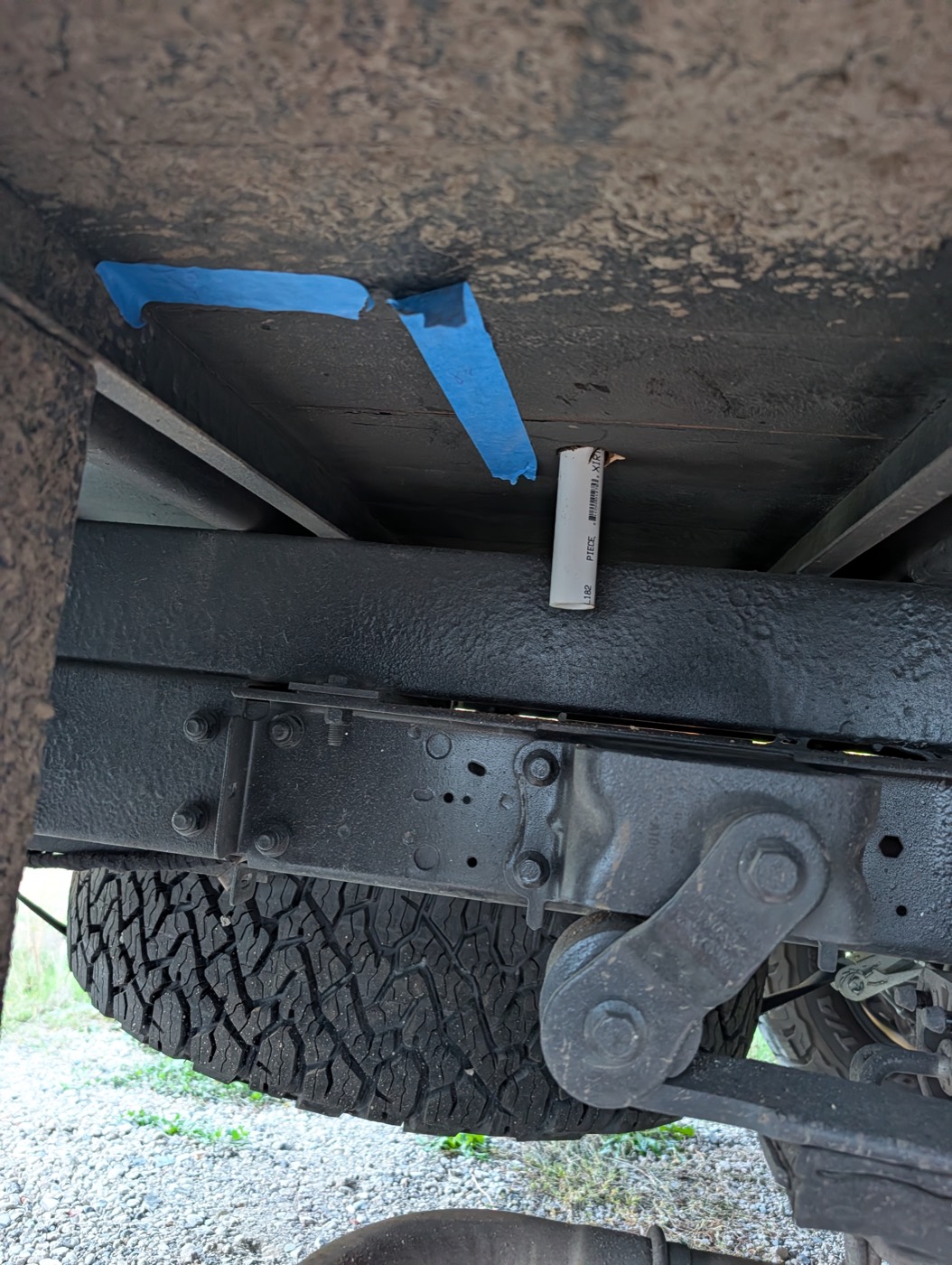
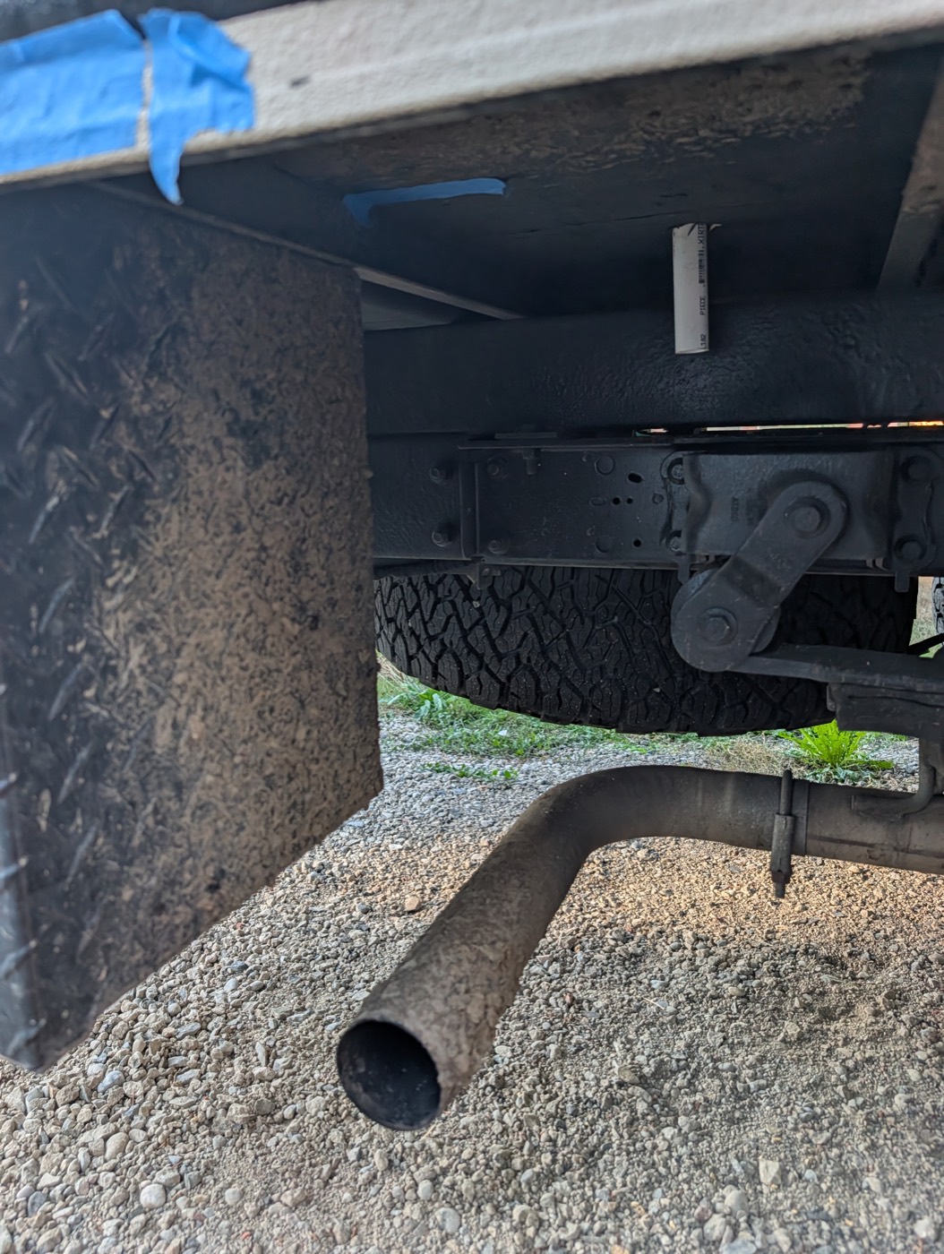
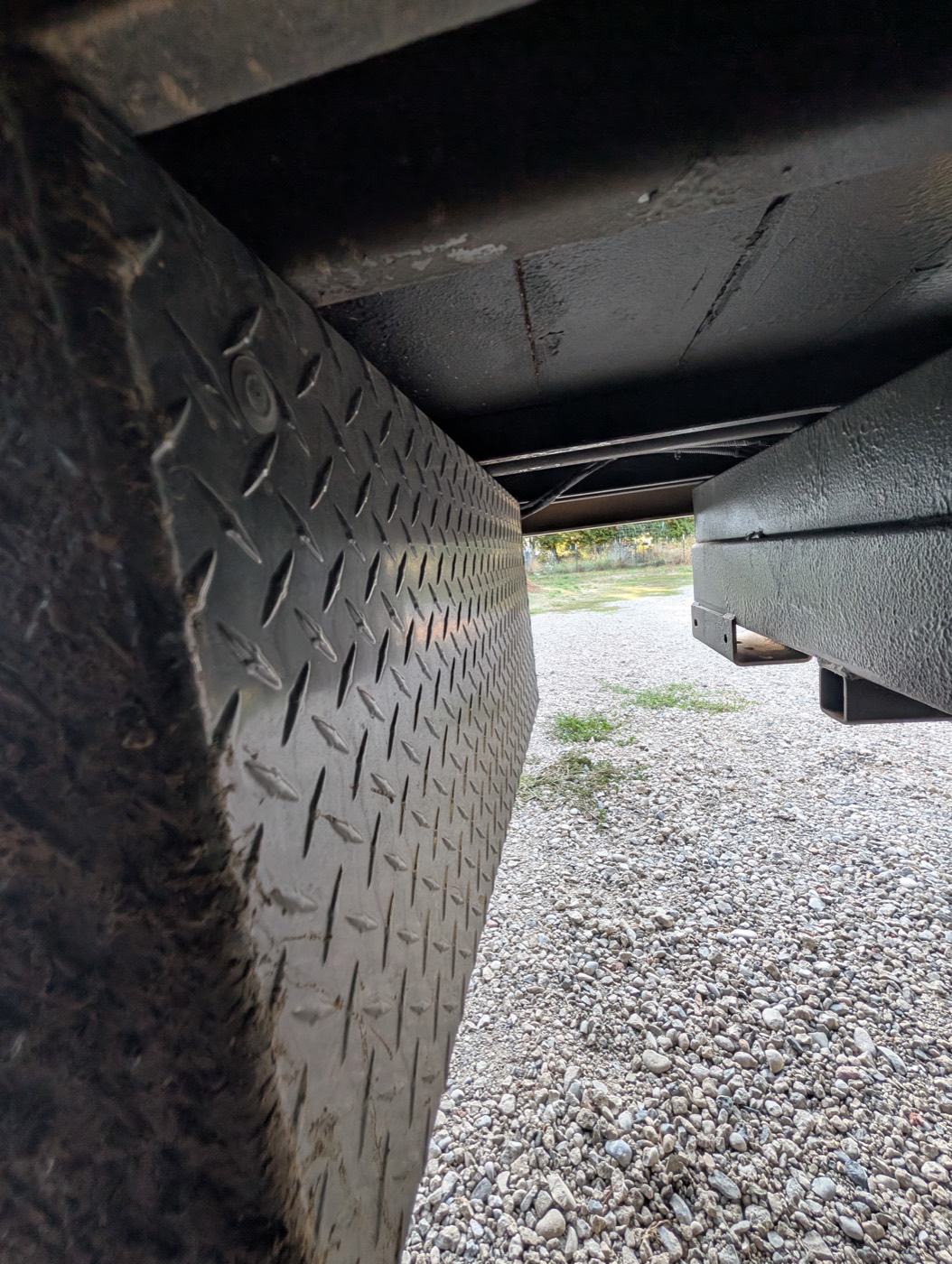
Two things the photographs settle. The crossmember sits immediately aft of H-1, so the rear row has less room than the plan assumed and every centre in it is provisional until the tape confirms it. And the outboard wall of the box is diamond plate facing the road, which is why the three lines that enter the box now go in through the BACK, not the side.
Lines that end in a joint go into the box, because a joint you cannot see is a joint you find as a stain. Lines that discharge stay outside it. Lines that are passing through get clamped and keep going.
The vent, and why it is 3/4 hose rather than 1/2 PEX
That line is the overflow, not just a vent. On air alone 1/2 would be plenty. Full, it has to swallow the entire fill rate without backing up, 5 to 8 GPM off a garden hose, and what backs up is pressure in a tank the vendor says is not pressurised. 1/2 PEX is 0.475 of bore against 0.75, less than half the area before a single crimp elbow, and PEX sags between supports on a line that must never hold water.
Up above the tank top first, then continuous fall. That peak sets your maximum fill, and the screened outlet below the floor is your level gauge: fill until it runs out of it.
The chain: T14, then M3, then T15, then T17, then H-4, then T16. At 6 GPM the tank port itself costs 0.75 psi; at 9 GPM, a hose wide open, it costs 1.69 psi and you are at the relief. So throttle the fill with F26 rather than fitting a relief valve nobody stocks.
The bay drain, and what it will and will not do
The bay is the lowest point in the water system and 41 gallons sit in it. A weep or a split has nowhere to go except the floor, the wiring and the box below. Hole 8 is the cheapest insurance on this page: one more cut while the saw is out.
A 1 1/4 in bore with an inch of standing water passes about 5 GPM, so a weeping fitting simply never accumulates. A split tank is 20 to 40 GPM, so the bay floods and the drain empties it over the next quarter hour. That is still the difference between a wet bay and water standing against the wiring.
The floor is flat, so give it a low point. Put a tray or a sealant curb under the fitting cluster, where a weep actually starts, and counterbore the top of the drain itself: about 1/4 in deep and 2 1/2 in across, into the top ply only, so the drain sits in a shallow dish rather than level with a flat floor. That is the difference between a hole in the floor and a drain.
The order matters, and step two is the one people skip. Bore the counterbore first with a Forstner or a hole saw run shallow. Then seal the raw ply in it, end grain and all, with epoxy or thinned sealant, and let it cure: that dish is going to be the wettest wood in the van and it is freshly cut. Then drill the 1 3/4 in through, bed the sleeve with its top flush with the BOTTOM of the dish, fillet it, and feather the sealant out to the floor so there is no lip to step over.
Finish it with a strainer, not a grommet. A grommet sitting below the surface just makes a second lip for water to sit behind. What kills a floor drain is debris, so what you want on top is something you can lift out and clean: a small stainless basket strainer dropped into the dish, or a disc of stainless mesh held by the sealant fillet.
And the other half of this is detection: a ten dollar water sensor tells you while it is still a cup.
7What is still open
- Where the strut runs across the patch, so the holes clear it and it stays free for a deck rail.
- The box wall thickness, and where on the back it is safe to cut three holes clear of its seams. The kit grommets go in those. The MATERIAL is settled: a magnet does not stick, so the box is aluminium, not steel (Jeff, 2026-09-20). Caliper the wall at the first pilot hole and this item closes.
- Where H-1's drip lands. Not whether it hits steel, which is fine: a few drips of fresh water on a coated frame is nothing next to the salt spray that corner already lives in. The question is whether it lands somewhere that TRAPS it, a seam or a lap joint or an open box section, because water that cannot dry is a different thing from water that runs off.
- The safety valve's discharge, confirmed with water rather than from a drawing: pressurise the cold side, turn the black knob one snap, watch where it comes out. Hole 1 goes under that.
8Every part named on this page
Tap or hover any id in the text and it will tell you what it is.
| id | part | where |
|---|---|---|
| F1 | 3/4 in Trident 162 potable hose, fill line | Hangs vertically off T12 and drops straight through the floor |
| F26 | Garden-hose flow restrictor washer, about 4 GPM | JEFF'S CALL 2026-09-17, and it replaces the relief valve T30 rather than joining it |
| H-1 | Isotemp safety valve drain | 1 1/8 in hole, beside the box |
| H-2 | Coolant SUPPLY to the engine | 1 3/8 in hole, past the box |
| H2 | 1/2 in FNPT swivel to PEX union | cold in |
| H-3 | Coolant RETURN from the engine | 1 3/8 in hole, past the box |
| H3 | 1/2 in FNPT swivel to PEX union | hot out |
| H-4 | Tank vent, and it is the overflow too | 2 in hole, beside the box |
| H-5 | Fill hose, inside a rigid sleeve | 2 in hole, into the box |
| H-6 | Outdoor shower HOT | 1 1/4 in hole, into the box |
| H7 | 3/8 in hose for the safety valve outlet | Isotemp spec: 3/8 in (10 mm) hose to a FREE outlet at a lower point, gravity only |
| H-7 | Outdoor shower COLD | 1 1/4 in hole, into the box |
| H-8 | BAY EMERGENCY DRAIN, nothing runs through it | 2 in hole, beside the box |
| H8 | 5/8 in heater hose, 210 F, antifreeze rated | 50 ft, plus 15 ft in the extra-long kit and 1 ft of 3/4 for the Transit |
| M3 | Stainless hose clamps, assorted | For the vent hose and the grey line |
| S9 | 1/2 in PEX ball valve, brass | outdoor shower · hot |
| S10 | Undermount box, ALREADY OWNED | ALREADY OWNED 2026-09-09 |
| S12 | Marine-rated line for this branch | Transition inside the envelope |
| T14 | 1/2 in MNPT x 3/4 in hose barb, nylon | Into N2, the top-right port |
| T15 | 3/4 in hose, vent | same coil as the fill line |
| T16 | Stainless mesh screen and clamp | Screens the vent outlet, pointing down |
| T17 | Cushioned P-clamps, stainless, with T-nuts | Three ~1 in ones pin the vent hose to the 8020 bay framing: above the barb, at the top of the arc, and holding the... |
| T33 | 1/2 in MIP x 1/2 in barb, brass | into the valve inlet |
| T35 | 1/2 in NPT plug, brass | caps the spare tee port |