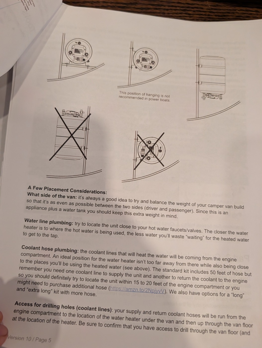
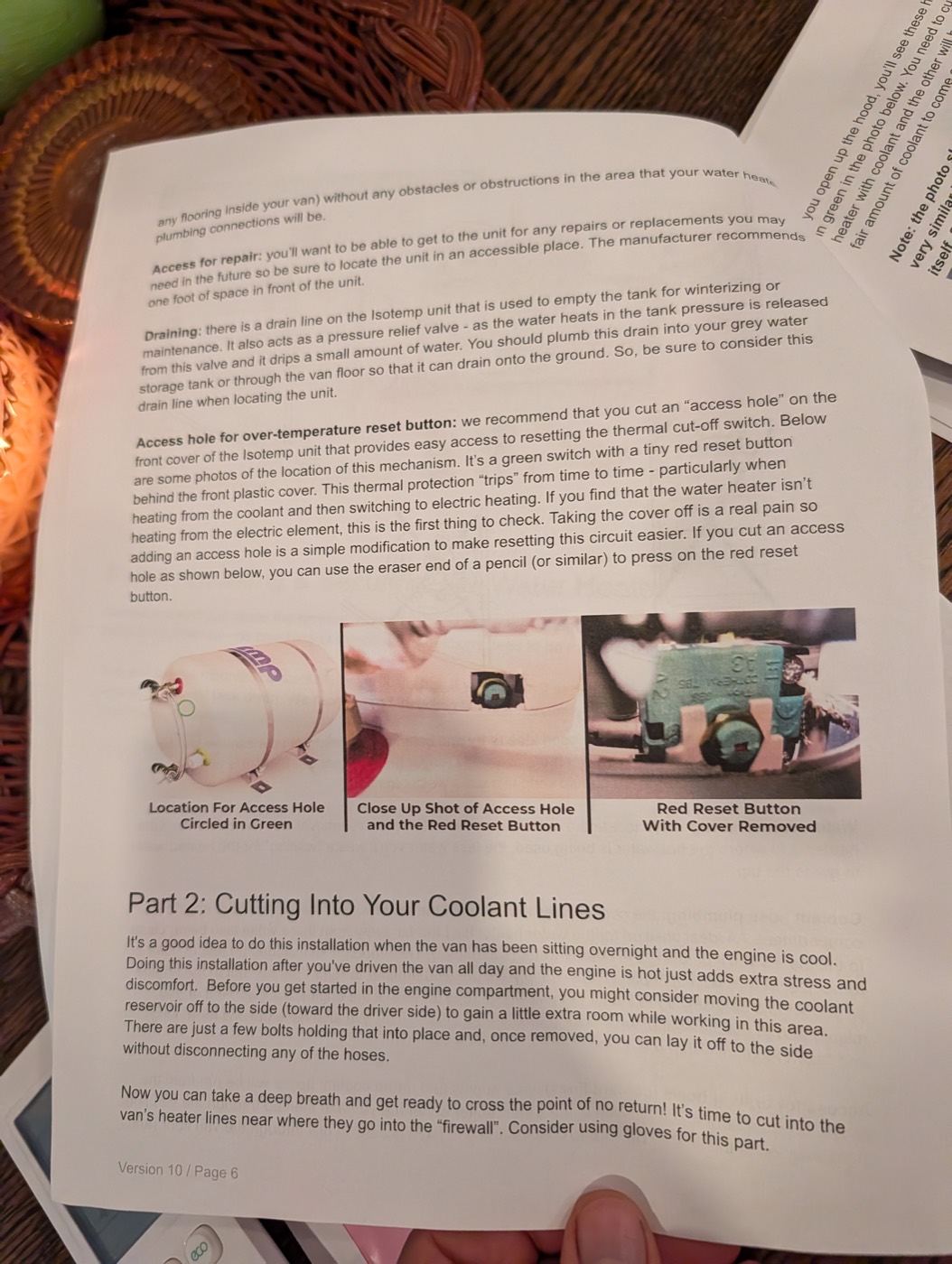
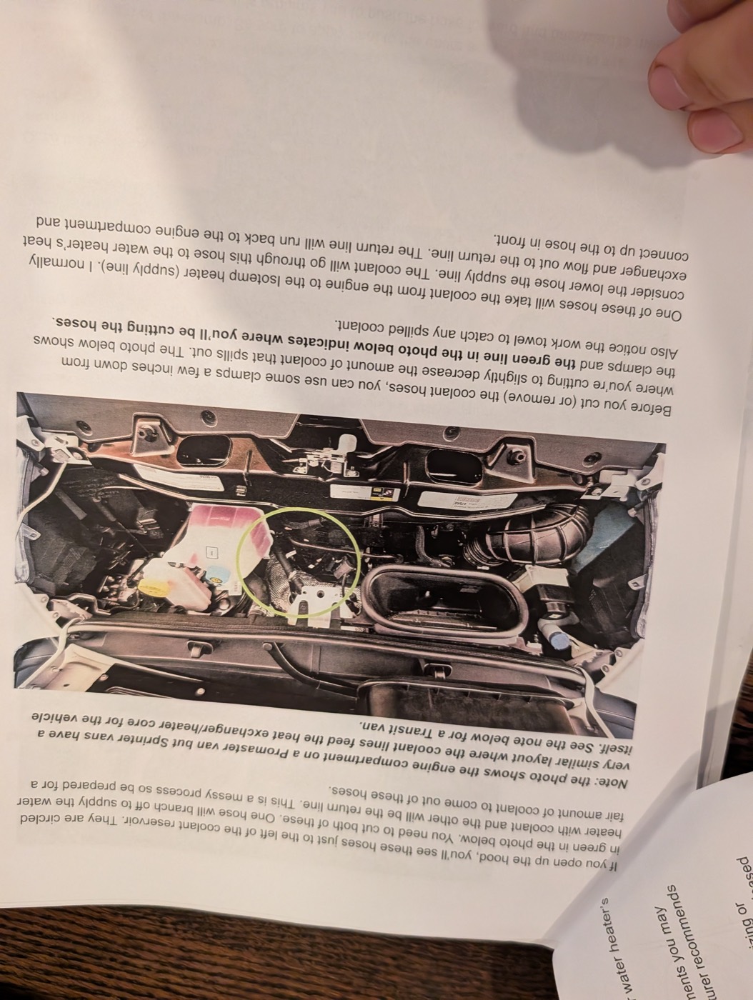
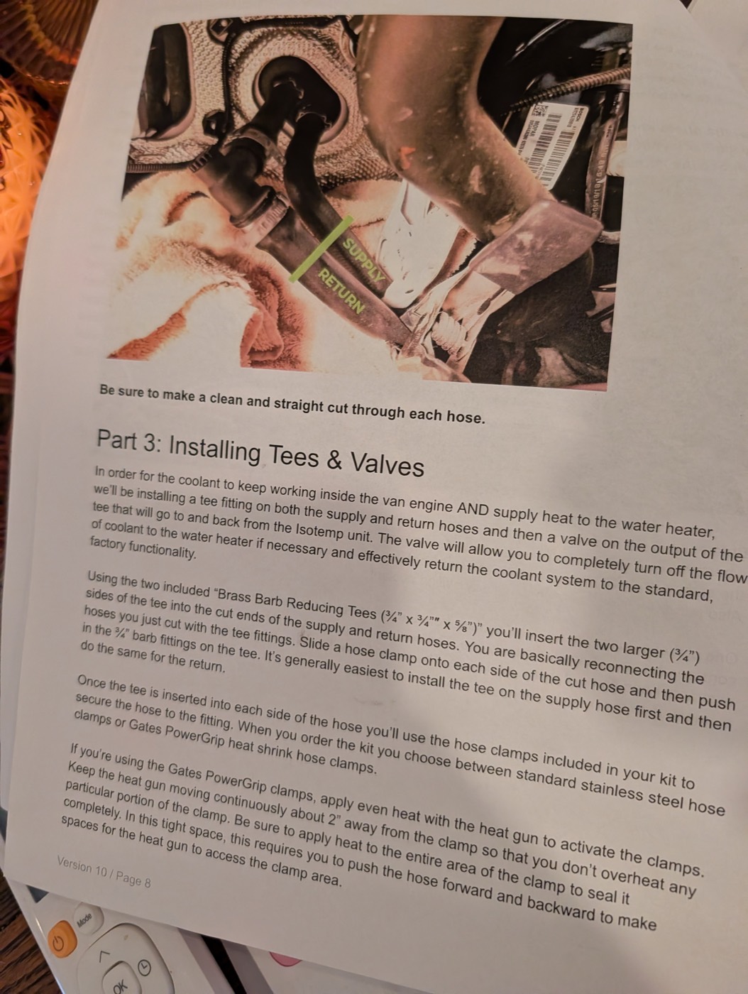
The kit's install guide
The printed instructions that came in the Isotemp kit, transcribed in full from photos of the pages, so the build has them next to everything else. First, the places where Tope does it differently. Then the guide itself, page by page, word for word.
Doing the install? Use the interactive manual: the same steps as a checklist, Tope's way.
This guide is written and published by Vanlife Outfitters, LLC, and it is theirs. It is reproduced here as this build's reference copy of the manual that shipped with the kit. Their own disclaimer applies: use it at your own risk, and read Isotemp's manual first.
1Where Tope departs from the guide
The guide is written for a Ram Promaster with a sheet-metal floor, and says itself that it is just a guide. Tope is a Transit cutaway with a 2 1/4 in cored floor and a Slim Square on its edge, so a few things change.
Coolant hose floor holes
The guideThe guide drills 1 3/4 in and glues in the kit's 1 1/4 x 3/4 PVC reducer bushings with red RTV.
TopeTope's coolant holes (H-2, H-3) are 1 3/8 in with a galvanised steel nipple as the sleeve, because that hose runs near 190 F and the floor is a 2 1/4 in sandwich with foam in it. The PVC bushings are cut for a single sheet-metal floor, not a cored one. more
Series or parallel
The guideThe guide is unambiguous that its kit goes in PARALLEL: a reducing tee on EACH heater hose, and its bleeding tip says outright that the cab heater loop and the water heater loop now split the pump's pressure between them.
TopeThis settles what the kit in hand is designed for. The build had this open since FarOutRide's Transit install cut once, in series. Parallel is what these parts do and what the plain ball valves suit; the Ford check is still worth doing, but it is now a confirmation rather than an open design question. more
Thread sealant
The guideThree different answers in one box: the guide text says Permatex 59214, the loose diagram sheet says Loctite 592, and the label on the unit itself says Loctite PST 592 or another high-temp thread sealer.
TopeIsotemp's own manual says Loctite 577 or Bondline T777. Use the heater manufacturer's, on the metal threads at the heater. Either way, give it the guide's 24 hours before coolant or water goes through. more
Mounting orientation
The guideThe guide recommends horizontal, and allows vertical only with the connections facing down.
TopeTope's Isotemp lies on edge in the core pocket, because the bench gives 18 1/2 in clear and the unit is 23 1/4 long. The one rule that binds every orientation: the safety valve and its drain stay the lowest point. more
Safety valve drain
The guideThe guide plumbs it through the floor with 1/2 in PEX or braided vinyl, or into the grey tank, and says in bold never to cap it.
TopeSame on Tope: H-1, cut 2026-09-19, a short PEX stub through a PVC sleeve, open, no screen, no cap. Tag it so nobody under the truck tries to stop the drip. more
The reset button
The guideThe guide says to cut an access hole in the front cover so the thermal cut-off's red reset can be pressed with a pencil, because it trips when switching from coolant to electric heat.
TopeFarOutRide said the same about their Transit install, independently. Two builds agreeing makes it worth doing before the cover goes back on for good. more
Pump pressure
The guideThe guide says nothing about it.
TopeThe Slim Square's manual caps the pump at 42 psi. The Shurflo 4008 shuts off at 55. Measure the real cut-out and turn it down, or fit a regulator, before the heater sees water. more
2The diagram
3The guide
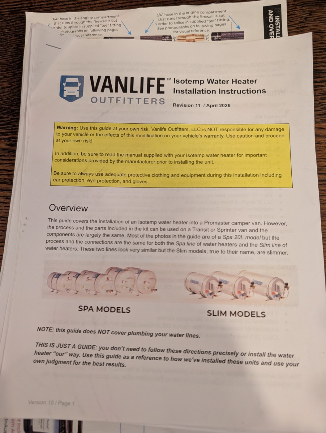
Vanlife Outfitters. Isotemp Water Heater Installation Instructions. Revision 11 / April 2026
Warning: Use this guide at your own risk. Vanlife Outfitters, LLC is NOT responsible for any damage to your vehicle or the effects of this modification on your vehicle's warranty. Use caution and proceed at your own risk!
In addition, be sure to read the manual supplied with your Isotemp water heater for important considerations provided by the manufacturer prior to installing the unit.
Be sure to always use adequate protective clothing and equipment during this installation including ear protection, eye protection, and gloves.
Overview
This guide covers the installation of an Isotemp water heater into a Promaster camper van. However, the process and the parts included in the kit can be used on a Transit or Sprinter van and the components are largely the same. Most of the photos in the guide are of a Spa 20L model but the process and the connections are the same for both the Spa line of water heaters and the Slim line of water heaters. These two lines look very similar but the Slim models, true to their name, are slimmer.
illustration: SPA MODELS / SLIM MODELS
NOTE: this guide does NOT cover plumbing your water lines.
THIS IS JUST A GUIDE: you don't need to follow these directions precisely or install the water heater "our" way. Use this guide as a reference to how we've installed these units and use your own judgment for the best results.
If you'd like to also watch a video of the install, WanderingWakes made a great video (https://www.youtube.com/watch?v=cFkOs8MyZFw) that you can watch that shows his installation which is very similar to what we recommend.
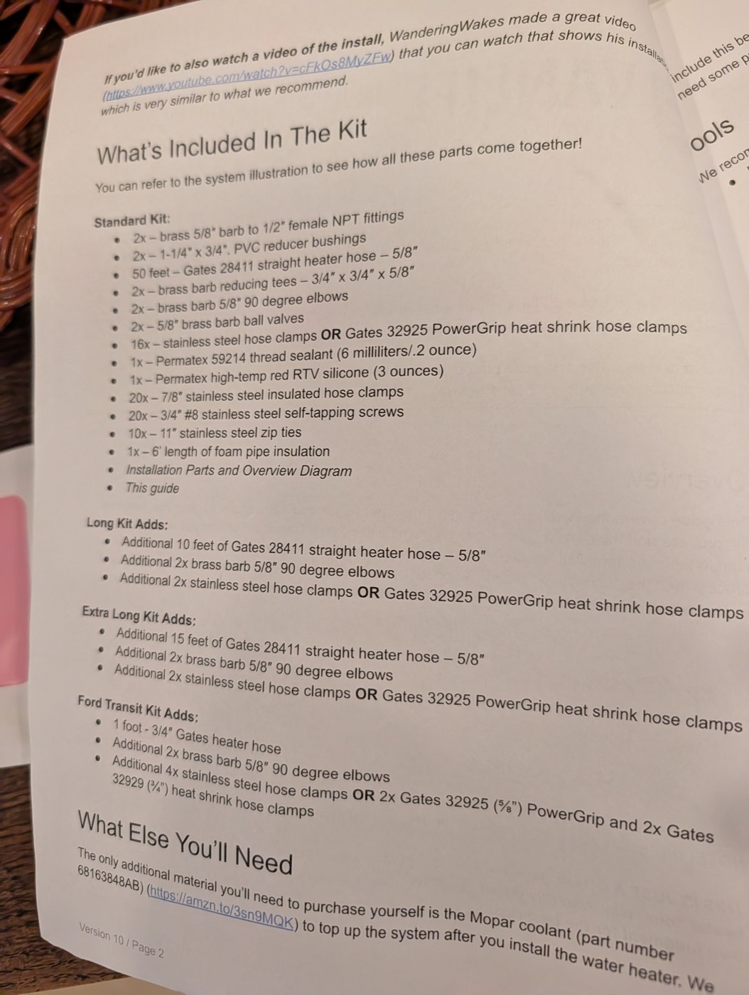
What's Included In The Kit
You can refer to the system illustration to see how all these parts come together!
Standard Kit:
- 2x brass 5/8" barb to 1/2" female NPT fittings
- 2x 1-1/4" x 3/4" PVC reducer bushings
- 50 feet, Gates 28411 straight heater hose, 5/8"
- 2x brass barb reducing tees, 3/4" x 3/4" x 5/8"
- 2x brass barb 5/8" 90 degree elbows
- 2x 5/8" brass barb ball valves
- 16x stainless steel hose clamps OR Gates 32925 PowerGrip heat shrink hose clamps
- 1x Permatex 59214 thread sealant (6 milliliters / .2 ounce)
- 1x Permatex high-temp red RTV silicone (3 ounces)
- 20x 7/8" stainless steel insulated hose clamps
- 20x 3/4" #8 stainless steel self-tapping screws
- 10x 11" stainless steel zip ties
- 1x 6' length of foam pipe insulation
- Installation Parts and Overview Diagram
- This guide
Long Kit Adds:
- Additional 10 feet of Gates 28411 straight heater hose, 5/8"
- Additional 2x brass barb 5/8" 90 degree elbows
- Additional 2x stainless steel hose clamps OR Gates 32925 PowerGrip heat shrink hose clamps
Extra Long Kit Adds:
- Additional 15 feet of Gates 28411 straight heater hose, 5/8"
- Additional 2x brass barb 5/8" 90 degree elbows
- Additional 2x stainless steel hose clamps OR Gates 32925 PowerGrip heat shrink hose clamps
Ford Transit Kit Adds:
- 1 foot, 3/4" Gates heater hose
- Additional 2x brass barb 5/8" 90 degree elbows
- Additional 4x stainless steel hose clamps OR 2x Gates 32925 (5/8") PowerGrip and 2x Gates 32929 (3/4") heat shrink hose clamps
What Else You'll Need
The only additional material you'll need to purchase yourself is the Mopar coolant (part number 68163848AB) (https://amzn.to/3sn9MQK) to top up the system after you install the water heater. We [continues on page 3] don't include this because of the weight and potential for liquid damage to the other components. You'll also need some paint or primer for covering the exposed metal of holes drilled.
Tools
We recommend you have the following tools available for your installation:
- Pipe cutter. This will help you get clean cuts on the coolant hose and will also come in handy when plumbing your water lines with something like Pex tubing. Example: https://amzn.to/39owhvU
- Heat gun. You'll need a heat gun to use the Gates heat shrink hose clamps. Example: https://amzn.to/36j5Ndv
- Adjustable wrenches. You'll use these to install the various threaded fittings. Example: https://amzn.to/37i6nHI
- Small bucket and towels. You'll be spilling some of the van's coolant when cutting into the lines so be ready to clean that up!
- 1/8" drill bit. This will be used to drill pilot holes for the larger holes the coolant lines will travel through into the van.
- 1-3/4" metal hole saw bit. You'll use this bit to make the holes for the coolant lines to enter the van through the floor that is large enough for the PVC bushings. Example: https://amzn.to/3qwORIC
- Round file. You'll need this to file the edges of the drilled holes. Example: https://amzn.to/3mo3ECP
- Funnel. You'll use this to add coolant into the hoses you run.
- Drill for creating the holes for the coolant hoses.
Installation Parts and Overview Diagram
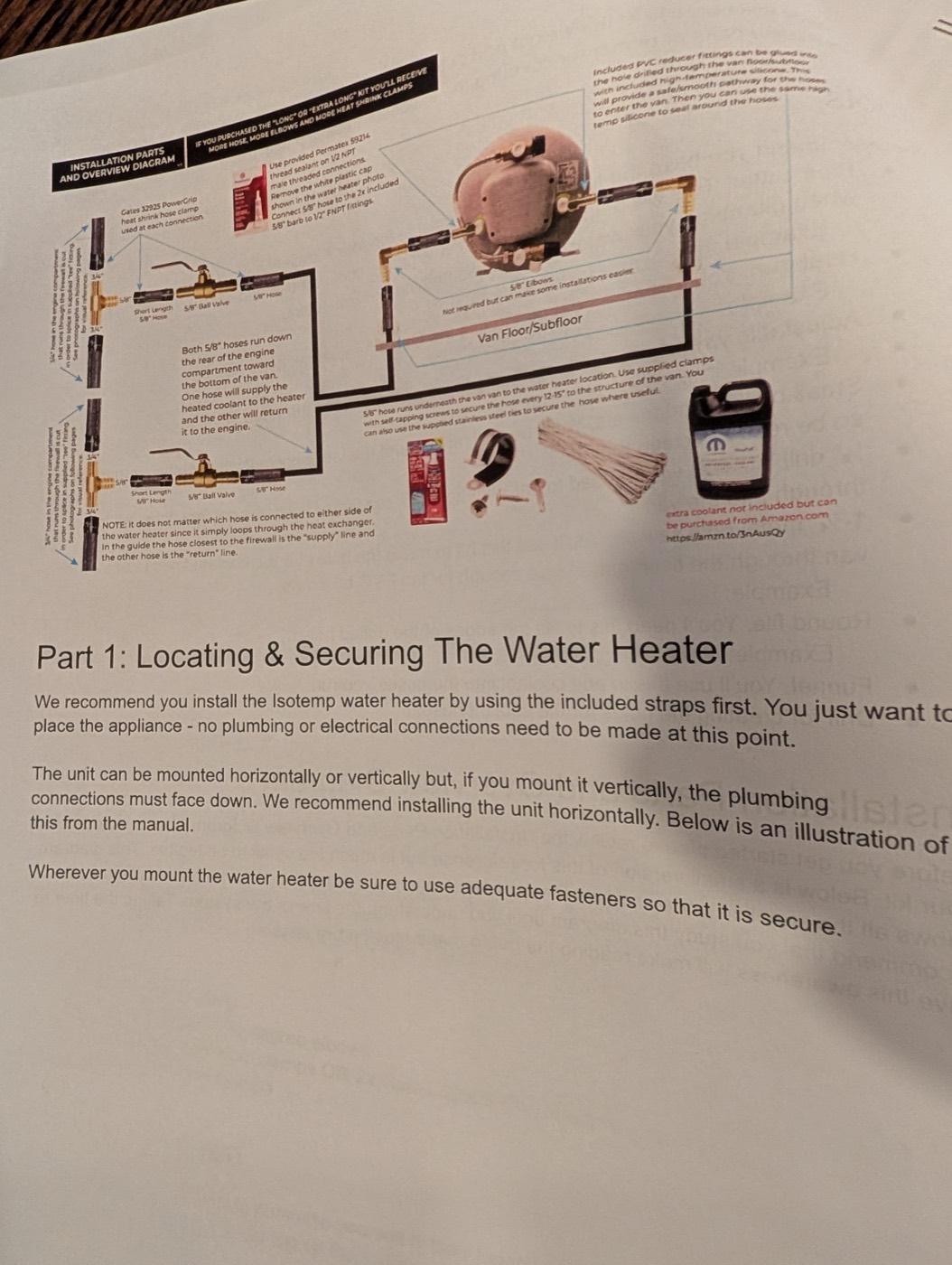
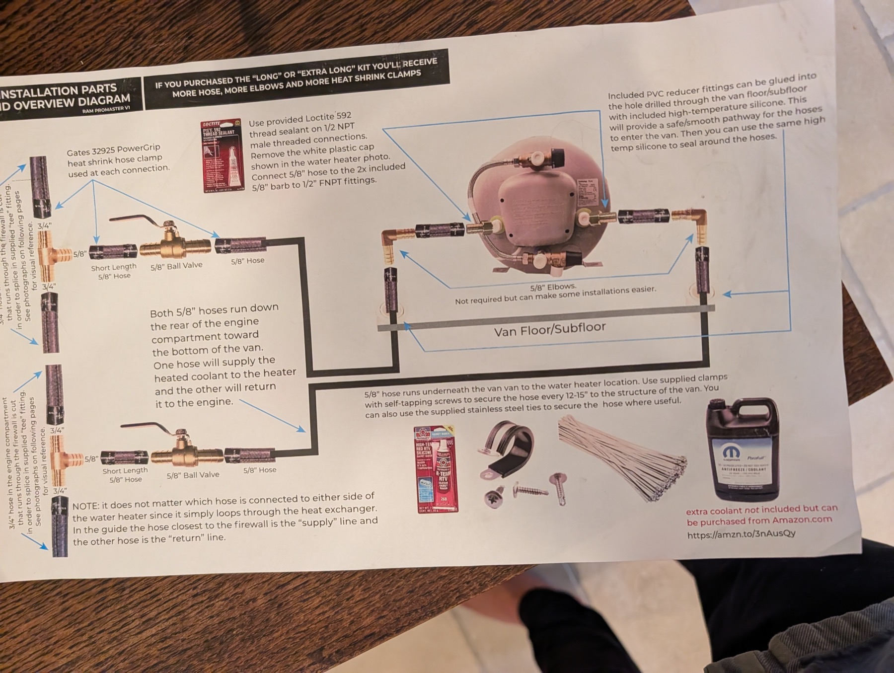
Before you get started please review the "Installation Parts and Overview Diagram" that is included in your kit. Below is a small version of this for reference but is much too small to be legible. This diagram shows all the supplied parts and how they connect up to each other to complete the installation. We recommend that you study this diagram until you understand the flow of the system. Taking the time to have this awareness will make reading the guide make much more sense!
Diagram: INSTALLATION PARTS AND OVERVIEW DIAGRAM. Callouts, as legible:
- "If you purchased the 'Long' or 'Extra Long' kit you'll receive more hose, more elbows and more heat shrink clamps"
- Left edge, both heater hoses: "3/4" hose in the engine compartment that runs through the firewall is cut in order to splice in supplied 'tee' fitting. See photographs on following pages for visual reference." A 3/4 x 3/4 x 5/8 tee is drawn on EACH of the two 3/4 hoses.
- "Gates 32925 PowerGrip heat shrink hose clamp used at each connection"
- Each tee branch: short length 5/8" hose, 5/8" ball valve, 5/8" hose.
- "Use provided Permatex 59214 thread sealant on 1/2 NPT male threaded connections. Remove the white plastic cap shown in the water heater photo. Connect 5/8" hose to the 2x included 5/8" barb to 1/2" FNPT fittings."
- "Both 5/8" hoses run down the rear of the engine compartment toward the bottom of the van. One hose will supply the heated coolant to the heater and the other will return it to the engine."
- "5/8" hose runs underneath the van to the water heater location. Use supplied clamps with self-tapping screws to secure the hose every 12-15" to the structure of the van. You can also use the supplied stainless steel ties to secure the hose where useful."
- "5/8" Elbows. Not required but can make some installations easier."
- "Van Floor/Subfloor"
- "Included PVC reducer fittings can be glued into the hole drilled through the van floor/subfloor with included high-temperature silicone. This will provide a safe/smooth pathway for the hoses to enter the van. Then you can use the same high temp silicone to seal around the hoses."
- "Extra coolant not included but can be purchased from Amazon.com https://amzn.to/3nAusQy"
- "NOTE: it does not matter which hose is connected to either side of the water heater since it simply loops through the heat exchanger. In the guide the hose closest to the firewall is the 'supply' line and the other hose is the 'return' line."
Part 1: Locating & Securing The Water Heater
We recommend you install the Isotemp water heater by using the included straps first. You just want to place the appliance - no plumbing or electrical connections need to be made at this point.
The unit can be mounted horizontally or vertically but, if you mount it vertically, the plumbing connections must face down. We recommend installing the unit horizontally. Below is an illustration of this from the manual.
Wherever you mount the water heater be sure to use adequate fasteners so that it is secure.
Illustration from the Isotemp manual: five mounting positions. Allowed: horizontal on a floor shelf; horizontal hung on a wall ("This position of hanging is not recommended in power boats."); vertical with the connections facing DOWN. Crossed out: vertical with the connections facing UP; horizontal rotated so the connections sit on the side.
A Few Placement Considerations:
What side of the van: it's always a good idea to try and balance the weight of your camper van build so that it's as even as possible between the two sides (driver and passenger). Since this is an appliance plus a water tank you should keep this extra weight in mind.
Water line plumbing: try to locate the unit close to your hot water faucets/valves. The closer the water heater is to where the hot water is being used, the less water you'll waste "waiting" for the heated water to get to the tap.
Coolant hose plumbing: the coolant lines that will heat the water will be coming from the engine compartment. An ideal position for the water heater isn't too far away from there while also being close to the places you'll be using the heated water (see above). The standard kit includes 50 feet of hose but remember you need one coolant line to supply the unit and another to return the coolant to the engine so you should definitely try to locate the unit within 15 to 20 feet of the engine compartment or you might need to purchase additional hose (https://amzn.to/2NpjyvV). We also have options for a "long" and "extra long" kit with more hose.
Access for drilling holes (coolant lines): your supply and return coolant hoses will be run from the engine compartment to the location of the water heater under the van and then up through the van floor at the location of the heater. Be sure to confirm that you have access to drill through the van floor (and
any flooring inside your van) without any obstacles or obstructions in the area that your water heater plumbing connections will be.
Access for repair: you'll want to be able to get to the unit for any repairs or replacements you may need in the future so be sure to locate the unit in an accessible place. The manufacturer recommends one foot of space in front of the unit.
Draining: there is a drain line on the Isotemp unit that is used to empty the tank for winterizing or maintenance. It also acts as a pressure relief valve - as the water heats in the tank pressure is released from this valve and it drips a small amount of water. You should plumb this drain into your grey water storage tank or through the van floor so that it can drain onto the ground. So, be sure to consider this drain line when locating the unit.
Access hole for over-temperature reset button: we recommend that you cut an "access hole" on the front cover of the Isotemp unit that provides easy access to resetting the thermal cut-off switch. Below are some photos of the location of this mechanism. It's a green switch with a tiny red reset button behind the front plastic cover. This thermal protection "trips" from time to time - particularly when heating from the coolant and then switching to electric heating. If you find that the water heater isn't heating from the electric element, this is the first thing to check. Taking the cover off is a real pain so adding an access hole is a simple modification to make resetting this circuit easier. If you cut an access hole as shown below, you can use the eraser end of a pencil (or similar) to press on the red reset button.
Photos: "Location For Access Hole Circled in Green" (on the front cover) / "Close Up Shot of Access Hole and the Red Reset Button" / "Red Reset Button With Cover Removed"
Part 2: Cutting Into Your Coolant Lines
It's a good idea to do this installation when the van has been sitting overnight and the engine is cool. Doing this installation after you've driven the van all day and the engine is hot just adds extra stress and discomfort. Before you get started in the engine compartment, you might consider moving the coolant reservoir off to the side (toward the driver side) to gain a little extra room while working in this area. There are just a few bolts holding that into place and, once removed, you can lay it off to the side without disconnecting any of the hoses.
Now you can take a deep breath and get ready to cross the point of no return! It's time to cut into the van's heater lines near where they go into the "firewall". Consider using gloves for this part.
If you open up the hood, you'll see these hoses just to the left of the coolant reservoir. They are circled in green in the photo below. You need to cut both of these. One hose will branch off to supply the water heater with coolant and the other will be the return line. This is a messy process so be prepared for a fair amount of coolant to come out of these hoses.
Note: the photo shows the engine compartment on a Promaster van but Sprinter vans have a very similar layout where the coolant lines feed the heat exchanger/heater core for the vehicle itself. See the note below for a Transit van.
Photo: Promaster engine bay, the two heater hoses circled in green beside the coolant reservoir.
Before you cut (or remove) the coolant hoses, you can use some clamps a few inches down from where you're cutting to slightly decrease the amount of coolant that spills out. The photo below shows the clamps and the green line in the photo below indicates where you'll be cutting the hoses. Also notice the work towel to catch any spilled coolant.
One of these hoses will take the coolant from the engine to the Isotemp heater (supply line). I normally consider the lower hose the supply line. The coolant will go through this hose to the water heater's heat exchanger and flow out to the return line. The return line will run back to the engine compartment and connect up to the hose in front.
Photo: the two heater hoses at the firewall, labelled SUPPLY and RETURN, a green line across both marking the cut, work towel underneath.
Be sure to make a clean and straight cut through each hose.
Part 3: Installing Tees & Valves
In order for the coolant to keep working inside the van engine AND supply heat to the water heater, we'll be installing a tee fitting on both the supply and return hoses and then a valve on the output of the tee that will go to and back from the Isotemp unit. The valve will allow you to completely turn off the flow of coolant to the water heater if necessary and effectively return the coolant system to the standard, factory functionality.
Using the two included "Brass Barb Reducing Tees (3/4" x 3/4" x 5/8")" you'll insert the two larger (3/4") sides of the tee into the cut ends of the supply and return hoses you just cut with the tee fittings. Slide a hose clamp onto each side of the cut hose and then push in the 3/4" barb fittings on the tee. You are basically reconnecting the hoses with the tee. It's generally easiest to install the tee on the supply hose first and then do the same for the return.
Once the tee is inserted into each side of the hose you'll use the hose clamps included in your kit to secure the hose to the fitting. When you order the kit you choose between standard stainless steel hose clamps or Gates PowerGrip heat shrink hose clamps.
If you're using the Gates PowerGrip clamps, apply even heat with the heat gun to activate the clamps. Keep the heat gun moving continuously about 2" away from the clamp so that you don't overheat any particular portion of the clamp. Be sure to apply heat to the entire area of the clamp to seal it completely. In this tight space, this requires you to push the hose forward and backward to make spaces for the heat gun to access the clamp area.
If you have not used a Gates heat shrink hose clamp, we recommend you watch the following video. The actual installation portion of the video begins around 1 minute and 38 seconds. https://www.youtube.com/watch?v=4O91YqHbp8c
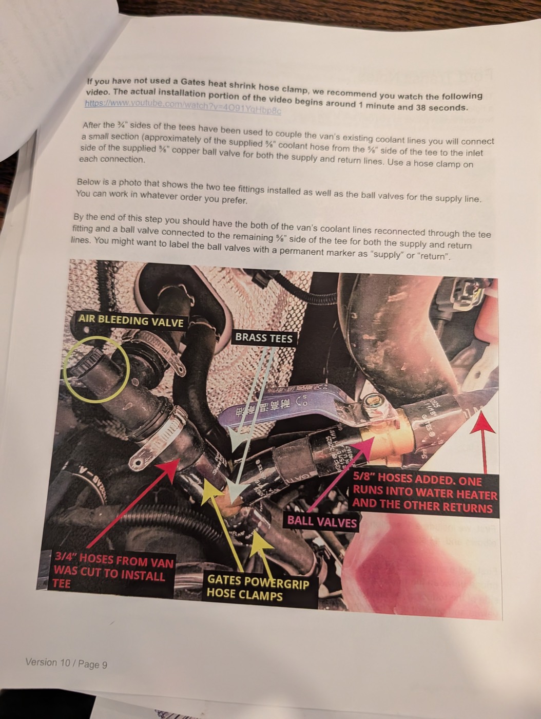
After the 3/4" sides of the tees have been used to couple the van's existing coolant lines you will connect a small section (approximately of the supplied 5/8" coolant hose [length missing in the original]) from the 5/8" side of the tee to the inlet side of the supplied 5/8" copper ball valve for both the supply and return lines. Use a hose clamp on each connection.
Below is a photo that shows the two tee fittings installed as well as the ball valves for the supply line. You can work in whatever order you prefer.
By the end of this step you should have the both of the van's coolant lines reconnected through the tee fitting and a ball valve connected to the remaining 5/8" side of the tee for both the supply and return lines. You might want to label the ball valves with a permanent marker as "supply" or "return".
Photo, labelled: AIR BLEEDING VALVE (circled, on the upper hose); BRASS TEES; BALL VALVES; GATES POWERGRIP HOSE CLAMPS; "3/4" HOSES FROM VAN WAS CUT TO INSTALL TEE"; "5/8" HOSES ADDED. ONE RUNS INTO WATER HEATER AND THE OTHER RETURNS".
Ford Transit Notes
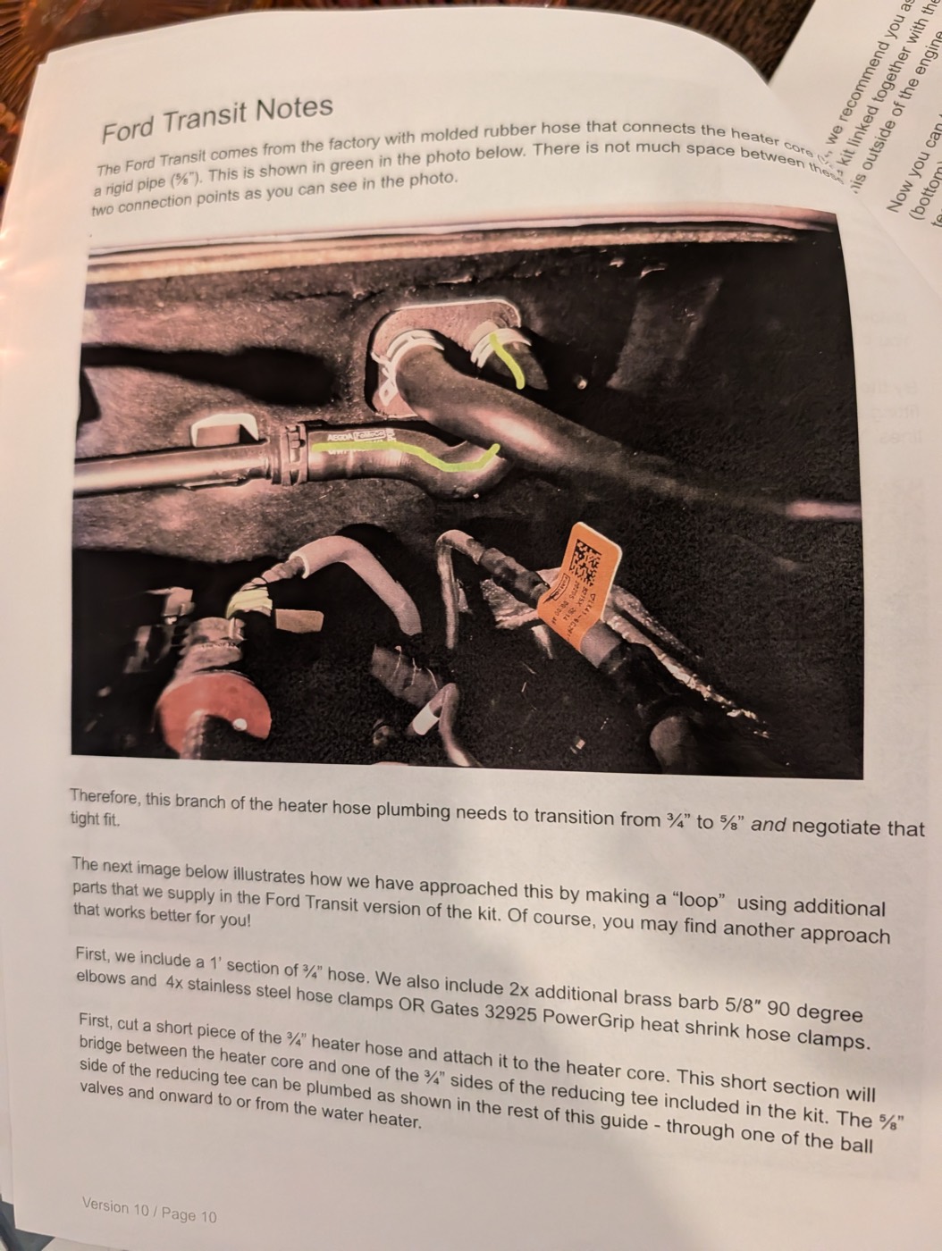
The Ford Transit comes from the factory with molded rubber hose that connects the heater core (3/4") to a rigid pipe (5/8"). This is shown in green in the photo below. There is not much space between these two connection points as you can see in the photo.
Photo: Transit firewall, the short molded rubber hose from the heater core to the rigid pipe highlighted in green.
Therefore, this branch of the heater hose plumbing needs to transition from 3/4" to 5/8" and negotiate that tight fit.
The next image below illustrates how we have approached this by making a "loop" using additional parts that we supply in the Ford Transit version of the kit. Of course, you may find another approach that works better for you!
First, we include a 1' section of 3/4" hose. We also include 2x additional brass barb 5/8" 90 degree elbows and 4x stainless steel hose clamps OR Gates 32925 PowerGrip heat shrink hose clamps.
First, cut a short piece of the 3/4" heater hose and attach it to the heater core. This short section will bridge between the heater core and one of the 3/4" sides of the reducing tee included in the kit. The 5/8" side of the reducing tee can be plumbed as shown in the rest of this guide - through one of the ball valves and onward to or from the water heater.
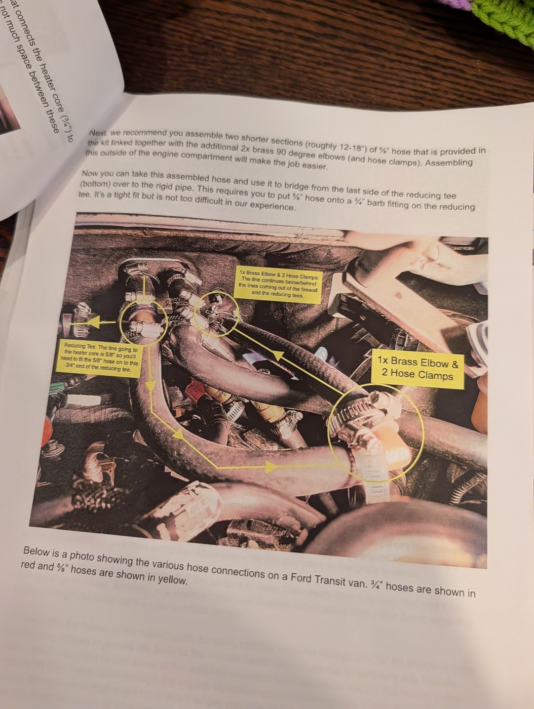
Next, we recommend you assemble two shorter sections (roughly 12-18") of 5/8" hose that is provided in the kit linked together with the additional 2x brass 90 degree elbows (and hose clamps). Assembling this outside of the engine compartment will make the job easier.
Now you can take this assembled hose and use it to bridge from the last side of the reducing tee (bottom) over to the rigid pipe. This requires you to put 5/8" hose onto a 3/4" barb fitting on the reducing tee. It's a tight fit but is not too difficult in our experience.
Photo, Transit engine bay, annotated in yellow: "Reducing Tee: The line going to the heater core is 5/8" so you'll need to fit the 5/8" hose on to this 3/4" end of the reducing tee." / "1x Brass Elbow & 2 Hose Clamps: The line continues below/behind the lines coming out of the firewall and the reducing tees." / "1x Brass Elbow & 2 Hose Clamps". Arrows trace the loop from the reducing tee, down and around, to the rigid pipe.
Below is a photo showing the various hose connections on a Ford Transit van. 3/4" hoses are shown in red and 5/8" hoses are shown in yellow.
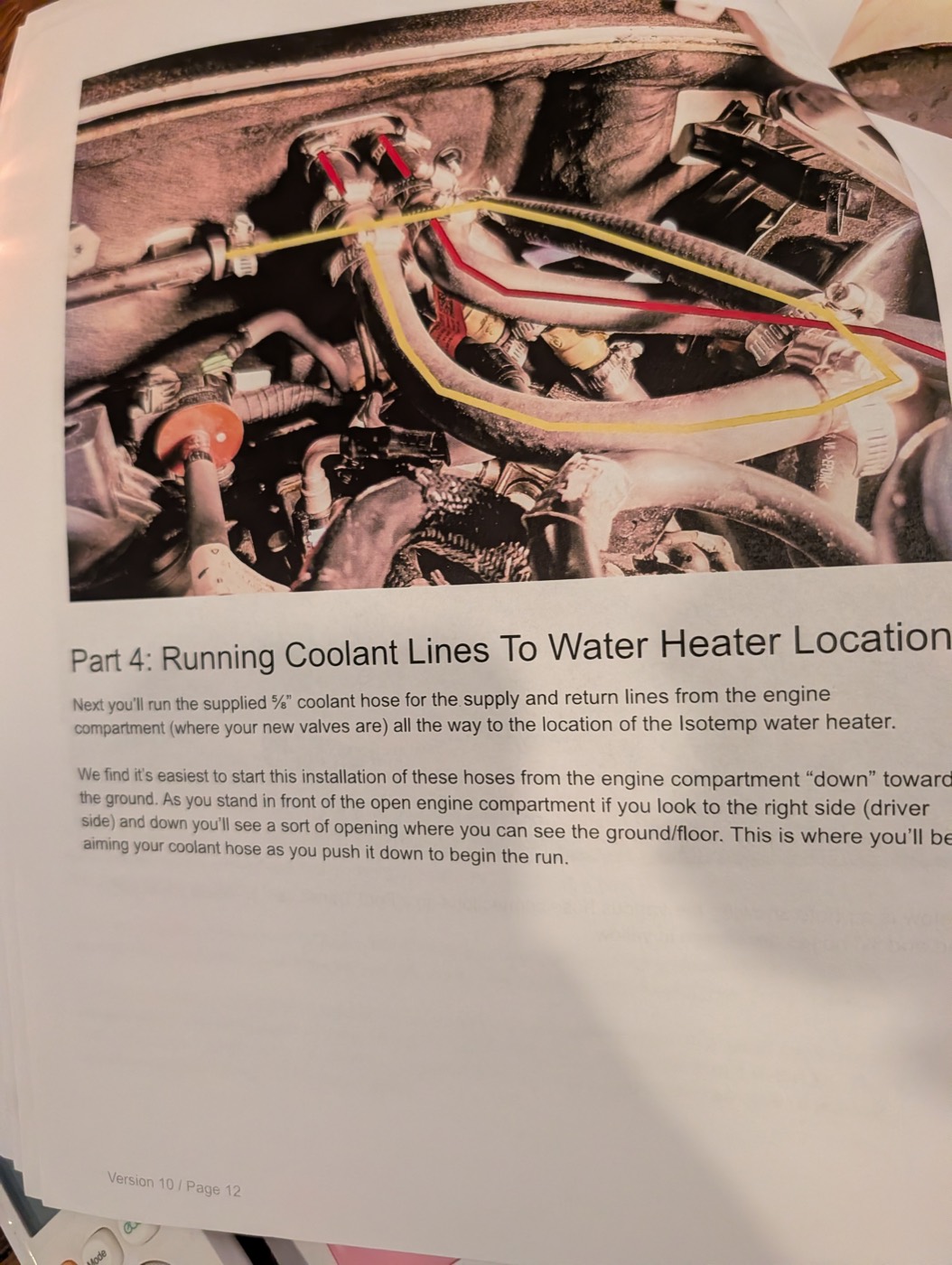
Photo: Ford Transit, finished connections. 3/4" hoses traced in red, 5/8" hoses traced in yellow, the yellow loop running from the reducing tee down and around to the rigid pipe.
Part 4: Running Coolant Lines To Water Heater Location
Next you'll run the supplied 5/8" coolant hose for the supply and return lines from the engine compartment (where your new valves are) all the way to the location of the Isotemp water heater.
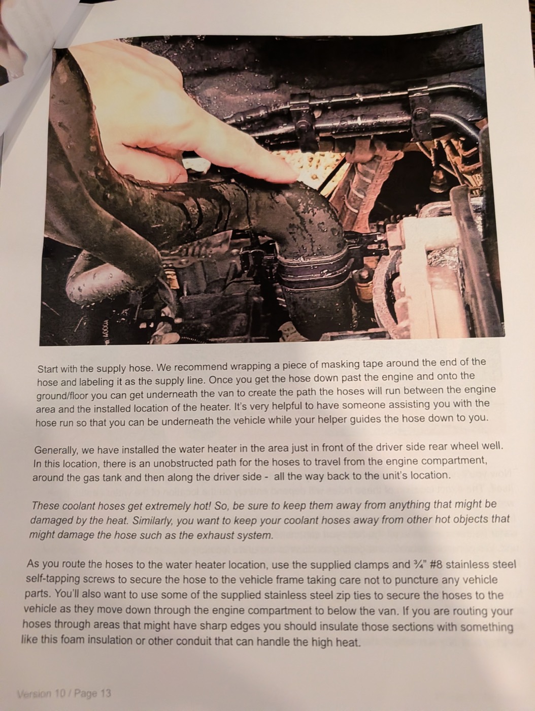
We find it's easiest to start this installation of these hoses from the engine compartment "down" toward the ground. As you stand in front of the open engine compartment if you look to the right side (driver side) and down you'll see a sort of opening where you can see the ground/floor. This is where you'll be aiming your coolant hose as you push it down to begin the run.
Photo: hand pushing the coolant hose down past the engine toward the ground.
Start with the supply hose. We recommend wrapping a piece of masking tape around the end of the hose and labeling it as the supply line. Once you get the hose down past the engine and onto the ground/floor you can get underneath the van to create the path the hoses will run between the engine area and the installed location of the heater. It's very helpful to have someone assisting you with the hose run so that you can be underneath the vehicle while your helper guides the hose down to you.
Generally, we have installed the water heater in the area just in front of the driver side rear wheel well. In this location, there is an unobstructed path for the hoses to travel from the engine compartment, around the gas tank and then along the driver side - all the way back to the unit's location.
These coolant hoses get extremely hot! So, be sure to keep them away from anything that might be damaged by the heat. Similarly, you want to keep your coolant hoses away from other hot objects that might damage the hose such as the exhaust system.
As you route the hoses to the water heater location, use the supplied clamps and 3/4" #8 stainless steel self-tapping screws to secure the hose to the vehicle frame taking care not to puncture any vehicle parts. You'll also want to use some of the supplied stainless steel zip ties to secure the hoses to the vehicle as they move down through the engine compartment to below the van. If you are routing your hoses through areas that might have sharp edges you should insulate those sections with something like this foam insulation or other conduit that can handle the high heat.
Image: cushioned P-clamp with self-tapping screw.
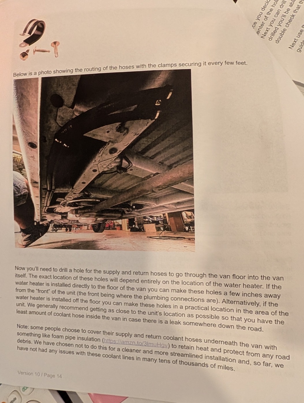
Below is a photo showing the routing of the hoses with the clamps securing it every few feet.
Photo: underside of the van, the two 5/8" hoses clamped along the frame.
Now you'll need to drill a hole for the supply and return hoses to go through the van floor into the van itself. The exact location of these holes will depend entirely on the location of the water heater. If the water heater is installed directly to the floor of the van you can make these holes a few inches away from the "front" of the unit (the front being where the plumbing connections are). Alternatively, if the water heater is installed off the floor you can make these holes in a practical location in the area of the unit. We generally recommend getting as close to the unit's location as possible so that you have the least amount of coolant hose inside the van in case there is a leak somewhere down the road.
Note: some people choose to cover their supply and return coolant hoses underneath the van with something like foam pipe insulation (https://amzn.to/3lmuHgv) to retain heat and protect from any road debris. We have chosen not to do this for a cleaner and more streamlined installation and, so far, we have not had any issues with these coolant lines in many tens of thousands of miles.
Once you decide where the holes for the coolant hoses should be placed, from inside the van, mark the center of the hole location and confirm that there are no obstructions below the van in that location! Next you can drill a small pilot hole at the two marked locations using a 1/8" drill bit. After the pilot hole is drilled you'll be able to go underneath the van and see exactly where the larger holes will be drilled and double check that the location is free of any obstacles.
Next use the 1-3/4" hole saw bit to create the larger holes from inside the van using the pilot holes as a guide. Once the holes are drilled, file the edges with a round file and then use paint or primer to seal and protect the exposed metal edges of the holes and let that dry. If it makes sense to you, you can continue onto some further steps while the primer/paint is drying.
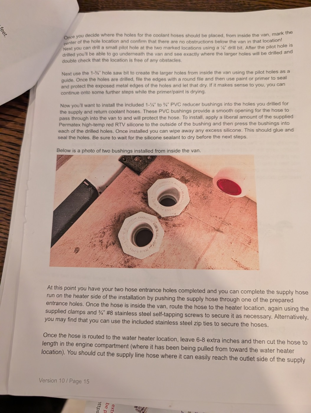
Now you'll want to install the included 1-1/4" to 3/4" PVC reducer bushings into the holes you drilled for the supply and return coolant hoses. These PVC bushings provide a smooth opening for the hose to pass through into the van to and will protect the hose. To install, apply a liberal amount of the supplied Permatex high-temp red RTV silicone to the outside of the bushing and then press the bushings into each of the drilled holes. Once installed you can wipe away any excess silicone. This should glue and seal the holes. Be sure to wait for the silicone sealant to dry before the next steps.
Below is a photo of two bushings installed from inside the van.
Photo: two white PVC reducer bushings seated in the plywood floor.
At this point you have your two hose entrance holes completed and you can complete the supply hose run on the heater side of the installation by pushing the supply hose through one of the prepared entrance holes. Once the hose is inside the van, route the hose to the heater location, again using the supplied clamps and 3/4" #8 stainless steel self-tapping screws to secure it as necessary. Alternatively, you may find that you can use the included stainless steel zip ties to secure the hoses.
Once the hose is routed to the water heater location, leave 6-8 extra inches and then cut the hose to length in the engine compartment (where it has been being pulled from toward the water heater location). You should cut the supply line hose where it can easily reach the outlet side of the supply
line's ball valve. We won't be connecting the hose to the ball valve yet so that we can add some coolant into the lines later.
Awesome, you're more than halfway done! Now you can repeat this process by routing the return coolant line from the engine compartment, down below the van all the way to the location of the water heater. You'll route this hose right next to the supply hose you already ran so it should go much quicker. You also already have the entrance hole prepared for this return line so you can push it through the entrance hole and complete the routing of the hose to the water heater location adjacent to the supply line. Now you should cut the return line hose to length where it easily reaches the outlet of the return line's ball valve. Once again, we won't connect the hose to the ball valve just yet.
After the hoses are fully routed, seal around the entrance holes where the hoses pass through the floor of the van with the included Permatex high-temp red RTV silicone.
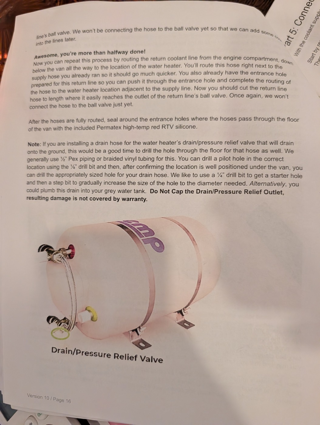
Note: If you are installing a drain hose for the water heater's drain/pressure relief valve that will drain onto the ground, this would be a good time to drill the hole through the floor for that hose as well. We generally use 1/2" Pex piping or braided vinyl tubing for this. You can drill a pilot hole in the correct location using the 1/8" drill bit and then, after confirming the location is well positioned under the van, you can drill the appropriately sized hole for your drain hose. We like to use a 1/4" drill bit to get a starter hole and then a step bit to gradually increase the size of the hole to the diameter needed. Alternatively, you could plumb this drain into your grey water tank. Do Not Cap the Drain/Pressure Relief Outlet, resulting damage is not covered by warranty.
Photo: Isotemp tank, the drain/pressure relief valve circled at the lower front. Caption: "Drain/Pressure Relief Valve".
Part 5: Connecting Coolant Lines To Water Heater
With the coolant supply and return lines installed, it's time to connect them up to the water heater itself!
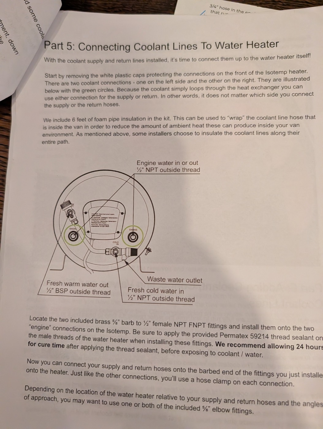
Start by removing the white plastic caps protecting the connections on the front of the Isotemp heater. There are two coolant connections - one on the left side and the other on the right. They are illustrated below with the green circles. Because the coolant simply loops through the heat exchanger you can use either connection for the supply or return. In other words, it does not matter which side you connect the supply or the return hoses.
We include 6 feet of foam pipe insulation in the kit. This can be used to "wrap" the coolant line hose that is inside the van in order to reduce the amount of ambient heat these can produce inside your van environment. As mentioned above, some installers choose to insulate the coolant lines along their entire path.
Diagram, front face of the Isotemp, the two ENGINE ports circled in green. Labels: "Engine water in or out, 1/2" NPT outside thread" (both engine ports); "Fresh warm water out, 1/2" BSP outside thread"; "Fresh cold water in, 1/2" NPT outside thread"; "Waste water outlet".
Locate the two included brass 5/8" barb to 1/2" female NPT FNPT fittings and install them onto the two "engine" connections on the Isotemp. Be sure to apply the provided Permatex 59214 thread sealant on the male threads of the water heater when installing these fittings. We recommend allowing 24 hours for cure time after applying the thread sealant, before exposing to coolant / water.
Now you can connect your supply and return hoses onto the barbed end of the fittings you just installed onto the heater. Just like the other connections, you'll use a hose clamp on each connection.
Depending on the location of the water heater relative to your supply and return hoses and the angles of approach, you may want to use one or both of the included 5/8" elbow fittings.
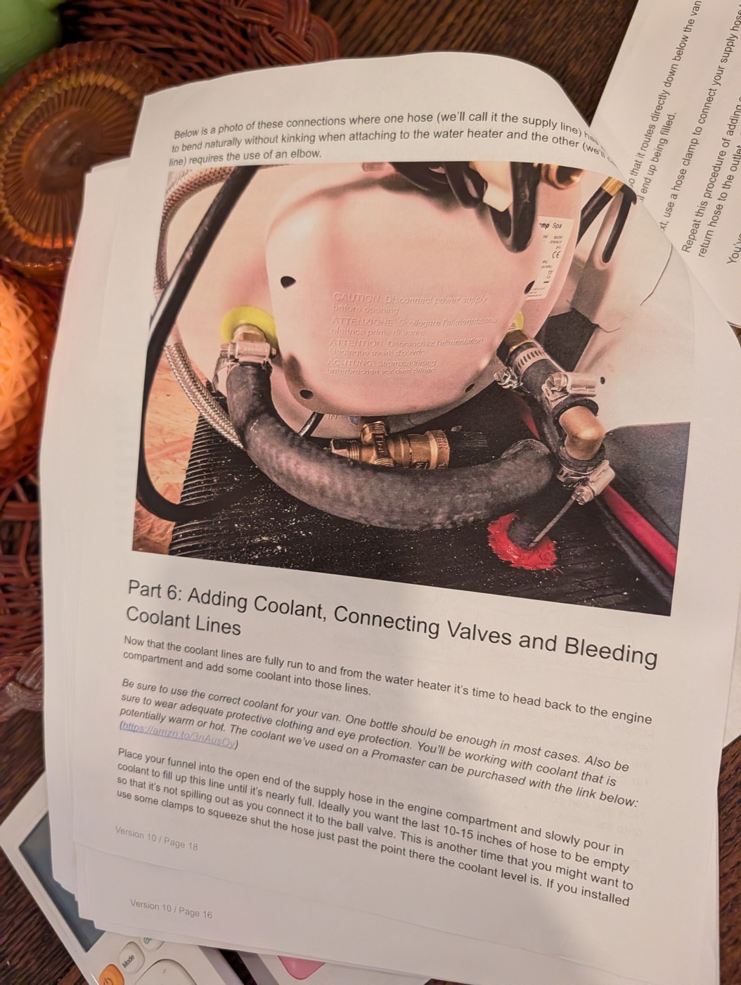
Below is a photo of these connections where one hose (we'll call it the supply line) has [room] to bend naturally without kinking when attaching to the water heater and the other (we'll call it the return line) requires the use of an elbow.
Photo: front of a Spa unit; one coolant hose loops round without an elbow, the other uses a 5/8" brass elbow; red RTV visible where a hose passes through the floor.
Part 6: Adding Coolant, Connecting Valves and Bleeding Coolant Lines
Now that the coolant lines are fully run to and from the water heater it's time to head back to the engine compartment and add some coolant into those lines.
Be sure to use the correct coolant for your van. One bottle should be enough in most cases. Also be sure to wear adequate protective clothing and eye protection. You'll be working with coolant that is potentially warm or hot. The coolant we've used on a Promaster can be purchased with the link below: (https://amzn.to/3nAusQy)
Place your funnel into the open end of the supply hose in the engine compartment and slowly pour in coolant to fill up this line until it's nearly full. Ideally you want the last 10-15 inches of hose to be empty so that it's not spilling out as you connect it to the ball valve. This is another time that you might want to use some clamps to squeeze shut the hose just past the point there the coolant level is. If you installed
[the] hose so that it routes directly down below the van as it leaves the engine compartment much of the hose will end up being filled.
Next, use a hose clamp to connect your supply hose to the outlet of the supply line ball valve.
Repeat this procedure of adding coolant to the return hose and use a hose clamp to connect your return hose to the outlet of the return line ball valve.
You've reached a moment of truth! It's time to turn on the van, test the connections, circulate the coolant through the system and bleed out any air.
Start by closing the ball valves for the supply and return lines and, if you moved the coolant reservoir out of the way during the installation you should move it back and re-fasten the bolts. You should have some towels ready and be sure to wear protective equipment like gloves and eye protection. It's also helpful to have someone assisting during this step who can be in the van to turn the engine on or off and throttle the engine as necessary.
When you're ready, have your assistant turn on the engine and let the engine idle while you check all the connections on the supply and return lines for any coolant leaks. Start by checking in the engine compartment around the tee fittings. If there are leaks, turn the engine off, clean the area around the leak and try using the heat gun to further shrink to tighten that connection and then repeat the test. If there are no leaks, slowly open the ball valves for the supply and return lines one at a time while the engine remains at idle. Check for any leaks around the ball valves and then check for leaks at any fittings inside the van including the connections to the water heater itself.
After you open the ball valves and the engine runs, coolant should slowly start circulating through the new lines and can lower the reservoir level since the newly installed heater hose needs to be filled up with coolant. So, while you're testing for leaks, ask your assistant to keep an eye on the coolant reservoir level and turn the engine off if it ever drops below the "low" mark. Then let the engine cool as needed and additional coolant to top off the reservoir and resume testing.
Tip: if you "clamp off" the coolant hoses just beyond where they go into the heater core the newly installed heater hose will fill up quicker by applying all the pressure from the pump to that "loop" exclusively. Now that you have the original heater "loop" and the new water heater "loop" you've basically split the pressure between the two. Clamping/pinching off the heater core loop temporarily makes the process of pumping coolant to the water heater and back quicker. These plastic pinch off clamps work very well for this purpose without damaging the hose: https://amzn.to/3aPJMre. Monitor the hoses near the clamps. When they begin warming up this is a signal that the coolant has its way to the water heater, through the water heater exchanger and all the way back to the engine compartment. When that happens, be sure to remove your clamps.
You may see bubbling in the coolant reservoir tank as air bleeds out of the system. This is normal.
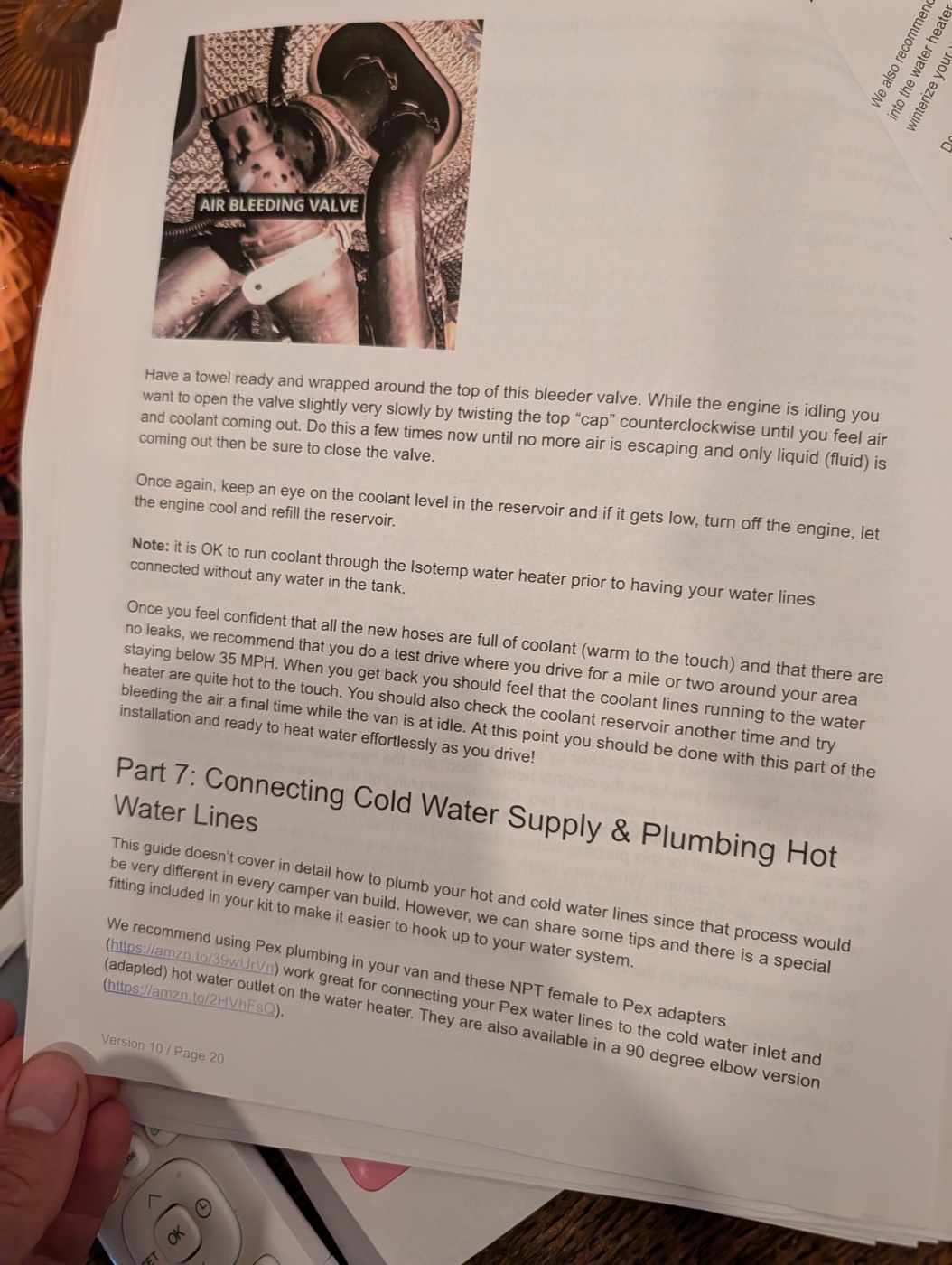
On a Promaster van, there is an air bleeding valve pictured below that can hasten the removal of any air in the coolant lines.
Photo: "AIR BLEEDING VALVE" on the Promaster coolant hose.
Have a towel ready and wrapped around the top of this bleeder valve. While the engine is idling you want to open the valve slightly very slowly by twisting the top "cap" counterclockwise until you feel air and coolant coming out. Do this a few times now until no more air is escaping and only liquid (fluid) is coming out then be sure to close the valve.
Once again, keep an eye on the coolant level in the reservoir and if it gets low, turn off the engine, let the engine cool and refill the reservoir.
Note: it is OK to run coolant through the Isotemp water heater prior to having your water lines connected without any water in the tank.
Once you feel confident that all the new hoses are full of coolant (warm to the touch) and that there are no leaks, we recommend that you do a test drive where you drive for a mile or two around your area staying below 35 MPH. When you get back you should feel that the coolant lines running to the water heater are quite hot to the touch. You should also check the coolant reservoir another time and try bleeding the air a final time while the van is at idle. At this point you should be done with this part of the installation and ready to heat water effortlessly as you drive!
Part 7: Connecting Cold Water Supply & Plumbing Hot Water Lines
This guide doesn't cover in detail how to plumb your hot and cold water lines since that process would be very different in every camper van build. However, we can share some tips and there is a special fitting included in your kit to make it easier to hook up to your water system.
We recommend using Pex plumbing in your van and these NPT female to Pex adapters (https://amzn.to/39wUrVn) work great for connecting your Pex water lines to the cold water inlet and (adapted) hot water outlet on the water heater. They are also available in a 90 degree elbow version (https://amzn.to/2HVhFsQ).
We also recommend putting a valve (https://amzn.to/36iqk1z) on the fresh/cold water line before it goes into the water heater. This will help you service the water heater if necessary and also help you winterize your van when needed. Some people also recommend a valve after the hot water outlet.
Depending on how many fixtures you have and how complex your plumbing system is, you might consider a Pex manifold with integrated valves (https://www.pexuniverse.com/sioux-chief-4-port-pex-copper-manifold-w-valves-672xv0490) so that each area of your plumbing can be selectively turned off if there are any leaks or repairs necessary.
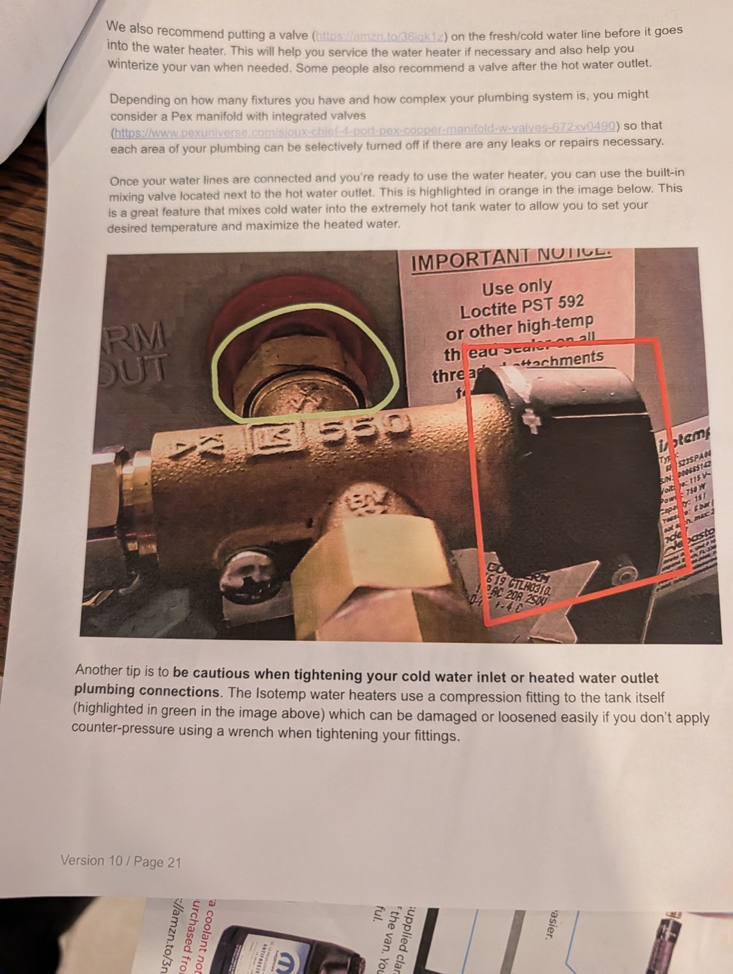
Once your water lines are connected and you're ready to use the water heater, you can use the built-in mixing valve located next to the hot water outlet. This is highlighted in orange in the image below. This is a great feature that mixes cold water into the extremely hot tank water to allow you to set your desired temperature and maximize the heated water.
Photo: close-up of the warm-water-out fitting. The compression fitting to the tank is circled in green; the mixing valve is boxed (in red/orange). A label on the unit reads "IMPORTANT NOTICE: Use only Loctite PST 592 or other high-temp thread sealer on all threaded attachments".
Another tip is to be cautious when tightening your cold water inlet or heated water outlet plumbing connections. The Isotemp water heaters use a compression fitting to the tank itself (highlighted in green in the image above) which can be damaged or loosened easily if you don't apply counter-pressure using a wrench when tightening your fittings.
Part 8: Electrical Connection
Well, this certainly is the easy part. The Isotemp water heater comes with a 750 watt (120 volt AC) electric heating element that can be used when you are not running the engine and want to heat water with electricity. Most people will only use this when they have some kind of shore/utility power connection since it consumes a lot of power if running from your batteries through an inverter.
To use this feature, simply plug the power cord into an active outlet! We recommend that when you design and install your electrical system you include an outlet near the water heater that is switched with something like this switch that has an LED indicator light (https://amzn.to/36IWDNr) when it's switched on so that you remember when you have the water heater's electric heating turned on.
Rest of page blank.
---
The large-format diagram that ships loose in the kit. Same drawing as page 4, legible. Callouts:
- "IF YOU PURCHASED THE 'LONG' OR 'EXTRA LONG' KIT YOU'LL RECEIVE MORE HOSE, MORE ELBOWS AND MORE HEAT SHRINK CLAMPS"
- "3/4" hose in the engine compartment that runs through the firewall is cut in order to splice in supplied 'tee' fitting. See photographs on following pages for visual reference." (Shown on BOTH 3/4" heater hoses: two tees.)
- "Gates 32925 PowerGrip heat shrink hose clamp used at each connection."
- Each tee's 5/8" branch: "Short Length 5/8" Hose", "5/8" Ball Valve", "5/8" Hose".
- "Use provided Loctite 592 thread sealant on 1/2 NPT male threaded connections. Remove the white plastic cap shown in the water heater photo. Connect 5/8" hose to the 2x included 5/8" barb to 1/2" FNPT fittings." (NOTE: the sheet says Loctite 592; the guide text says Permatex 59214.)
- "Both 5/8" hoses run down the rear of the engine compartment toward the bottom of the van. One hose will supply the heated coolant to the heater and the other will return it to the engine."
- "5/8" hose runs underneath the van to the water heater location. Use supplied clamps with self-tapping screws to secure the hose every 12-15" to the structure of the van. You can also use the supplied stainless steel ties to secure the hose where useful."
- "5/8" Elbows. Not required but can make some installations easier."
- "Van Floor/Subfloor"
- "Included PVC reducer fittings can be glued into the hole drilled through the van floor/subfloor with included high-temperature silicone. This will provide a safe/smooth pathway for the hoses to enter the van. Then you can use the same high temp silicone to seal around the hoses."
- "Extra coolant not included but can be purchased from Amazon.com https://amzn.to/3nAusQy"
- "NOTE: it does not matter which hose is connected to either side of the water heater since it simply loops through the heat exchanger. In the guide the hose closest to the firewall is the 'supply' line and the other hose is the 'return' line."
4The original pages
Jeff's photos of the printed guide, 2026-09-25. Tap one for full size.